The DC dual-arm bridge is a portable precision DC bridge with a wide range of Kelvin lines. The product is equipped with a zero indicator and can be supplied with a working power supply. It is suitable for the accurate measurement of DC low resistance in laboratories and research institutes of industrial and mining enterprises and research institutes, workshops or field work places. It is a designated product of the wire and cable industry regulations. QJ57P DC double-arm bridge technical parameters QJ57 is the same, using the international popular new shell. Determination of the resistance value of metal conductors for metal bars, sheets, cables, wires, etc. Inspection of welding quality of current busbars, metal casings, etc. Checksum adjustment for low resistance standards, DC shunts, power resistors, etc. Determination of switches, electrical appliances, contact resistance. For the DC resistance measurement of various types of motors and transformers, the contact resistance of brushes and switches, and the temperature rise test.
The DC dual-arm bridge, also known as the Kelvin bridge, is a small resistor suitable for measuring less than 1 Ω. In electrical engineering, it is often necessary to measure the conductivity of a metal, the resistance of a shunt, the resistance of a motor or a transformer winding, etc. When measuring these small resistances with a DC single-arm bridge, the wiring resistance and contact resistance are given. The measurement results bring errors that cannot be ignored. The DC dual-arm bridge is designed to eliminate and reduce this error. Figure 2 is a panel diagram of the DC dual-arm bridge QJ103.
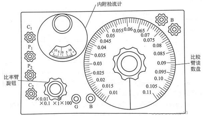
Figure 2 DC dual-arm bridge QJ103 type panel diagram
How does the DC dual-arm bridge work?The DC dual-arm bridge is also called the Kelvin bridge. The working principle circuit is shown in Figure 1. In the figure, Rx is the measured resistance and Rn is the adjustable resistor for comparison. Rx and Rn each have two pairs of terminals, C1 and C2, Cn1 and On2 are their current terminals, and P1 and P2, Pn1 and Pn2 are their potential terminals. When wiring, the measured resistance Rx must be between the potential terminals P1 and P2, and the current terminal is on the outside of the potential terminal. Otherwise, the influence of the wiring resistance and contact resistance on the measurement result cannot be eliminated and reduced. The current terminal Cn2 for comparing the adjustable resistor and the current terminal C2 of the resistor to be tested are connected by a thick wire having a resistance r. R1, R1', R2, and R2' are bridge arm resistances, and their resistance values ​​are all above 10 Ω. Structurally, R1 and R'1 and R2 and R2' are made into coaxial adjustment resistors, so that R1' and R2' are changed, and R1' and R2' are also changed, and can be maintained at all times.
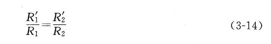
When measuring, connect RX to adjust the resistance of each bridge arm to balance the bridge. At this time, because Ig=0, the measured resistance Rx is obtained.
It can be seen that the measured resistance Rx is determined only by the ratio of the bridge arm resistances Rz and R1 and the comparison adjustable resistor Rn regardless of the thick wire resistance r. The ratio R2/R1 is called the magnification of the DC dual-arm bridge. So when the bridge is balanced
Measured resistance value = magnification reading × comparison with adjustable resistance reading
Therefore, in order to ensure the accuracy of the measurement, the wires connecting the Rx and Rn current terminals should use wires with good electrical conductivity and short and thick.
As long as it can guarantee  R1, R1', R2 and R2' are all larger than 1OΩ, r is small, and the wiring is correct. The DC double-arm bridge can better eliminate or reduce the influence of wiring resistance and contact resistance. Therefore, when measuring a small resistance with a DC dual-arm bridge, a more accurate measurement result can be obtained.
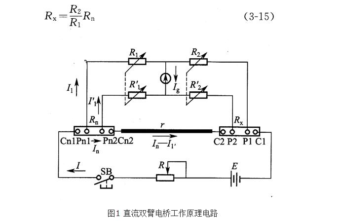
The DC double-arm bridge is a bridge for measuring low-resistance. When using a DC double-arm bridge, in addition to observing the use of the DC single-arm bridge, it should also be noted that since the double-arm bridge has P1, P2, C1, C2 four tested resistor terminals, where P1 and P2 are called potential terminals, and C1 and C2 are called current terminals. The measured resistance Rx should be correctly connected to the voltage and current terminals of the bridge. The current terminal of the measured resistance should be connected to C1 and C2 of the bridge, and the voltage terminal should be connected to P1 and P2 of the bridge. If the measured resistance is not specially wired, try to draw two wires at each end, respectively connecting the voltage terminal and the current terminal, as shown in Figure 8-7. And the lead should be as short and thick as possible, and the contact should be good. The voltage connector should be closer to the measured resistance Rs than the current connector, and the operation should be fast when measuring.
Figure 8-7 Measuring wire resistance wiring diagram
DC dual-arm bridge use precautions1 DC double-arm bridge has four terminals, namely Pl, P2, C1, C2, where P1 and P2 are potential terminals, and C1 and C2 are current terminals. The current terminal and potential terminal of the measured resistance should be correctly connected to the corresponding end of the double-arm bridge. When the measured resistance does not have a special potential terminal and current terminal, try to connect the four wires to the double-arm bridge, and connect the pair of wires on the inner side of the bridge with the pair of wires. The two pairs of connectors cannot be twisted. Together, the wiring diagram is shown in Figure 3.

Figure 3 DC dual-arm bridge QJ103 type panel diagram
2 The connecting wire should be as short and thick as possible. The wire joint should be cleaned of dirt, should be in good contact, and should be firmly connected to minimize contact resistance to improve measurement accuracy.
3 DC double-arm bridge has a large working current. When measuring, the “B†button should not be locked. When using the battery to measure, the operation speed should be fast to avoid excessive power consumption. Immediately after the measurement is completed, the power should be turned off.
Square Pin Header Connector Series
Square Pin Header Connector Series,Pin Connector,Square Pin Header Connector,Pin Header Connector Series
Dongguan ZhiChuangXing Electronics Co., LTD , https://www.zcxelectronics.com