A differential signal is a circuit that uses only two signal lines to transmit one signal. The circuit that relies on the voltage difference between signals can be either an analog signal or a digital signal. The actual signals are analog signals, and the digital signals are only the samples of the analog signal quantized by the threshold level. Therefore, differential signals can be defined for both digital and analog signals.
A differential signal uses a value to represent the difference between two physical quantities. Strictly speaking, all voltage signals are differential because one voltage can only be relative to the other. In some systems, the system "ground" (GND) is used as the voltage reference point. When "ground" is used as a voltage measurement reference, this signal planning is called single-ended. We use this term because the signal is represented by the voltage on a single conductor.
VDS is not a fast transmission rate and is highly resistant to interference. When there is a signal, one line voltage +V, the other line voltage -V, the signal obtained at the receiving end is the difference between the two +V-(-V)=2V. The external interference signal is the +v signal of the same amplitude and polarity on the middle of the two lines, which cancel each other out in the process of receiving the difference. Due to the strong anti-interference ability, the digital signal is not easy to make mistakes, and the retransmission caused by the verification error can be avoided. In this sense, the differential signal transmission rate.
The concept of difference has been learned in the Analog Circuits course. A differential signal is a pair of symmetric signals of equal magnitude and opposite polarity, and a differential signal is used to transmit a useful signal. The common mode signal is a pair of signals of the same magnitude and polarity acting on the differential signal line, and the common mode signal often comes from external interference. The differential signal is detected at the receiving end by a differential amplifier. The differential amplifier only amplifies the difference between the two input signals, and does not contribute to the potential of the two input signals to ground.
Differentially transmitted signals provide strong immunity to external interference.
The original input signal passes through the inverter and the buffer to form a pair of differential signals of equal magnitude and opposite polarity. For analog signals, the inverter can be implemented with an inverting proportional amplifier circuit of the operational amplifier, and the buffer can be implemented with the in-phase follower circuit of the operational amplifier. Digital signals can be implemented using "non-gate" logic and in-phase buffers, respectively.
The differential signals are arranged on the PCB (printed circuit board) as "close parallel lines" (PCB wiring essentials!), and the parallel connection or twisted pair is used when connecting two devices with cables. In the differential signal transmission process, an external interference signal is encountered. However, since the two differential signal lines are always together, the interference signal generally acts on the two signal lines at the same time, forming an equal phase on the two signal lines. The same common mode signal.
At the receiving end, the differential amplifier is only sensitive to differential signals (useful signals) and suppresses common mode signals (interfering signals). In this way, the differentially transmitted signal has strong anti-interference ability, so it is especially suitable for medium and long distance communication or high speed communication. In contrast, the two signal lines TXD and RXD of the UART are not suitable for long-distance communication. Because they are not differential signals, the signal will be severely distorted when external interference is encountered. At the receiving end, the sum of the useful signals cannot be distinguished. Interference signals can create a large number of errors.
Simply put, the differential signal is the difference between two related signals. This article describes the voltage differential signal, which has been widely used for audio, data transmission and electricity.
In the words. Although more complex than a single-ended input signal system, the advantages of a differential signaling system are significant. First, differential signals are highly immune to external electromagnetic interference (EMI). An interference source has the same effect on each end of the differential signal pair. Because the signal is determined by the voltage difference, the interference on both sides is offset, and the signal does not change significantly. Second, the differential signal facilitates the identification of small signals. In the differential signal system, the reference point is determined by the user, and the average signal of the two inputs can be selected as the reference point, which reduces the swing range of the signal. Third, the signal of the single-ended input system relies on virtual ground, and the differential signal does not need such a virtual ground, which increases the fidelity and stability of the bipolar signal. Fourth, the timing of the differential signals is accurately located. Differential signals are less affected by process and ambient temperatures, reducing timing errors. The current popular LVDS is a small amplitude differential signaling technology.
A differential amplifier is a device that accepts and outputs a differential signal. Like an op amp, it can accept a double-ended input, except that it has dual outputs, unlike op amps that have only a single port. In a differential amplifier, its output common-mode voltage (VOCM) can be independently controlled by a differential voltage. Figure 1 is a simplified schematic of a differential amplifier.
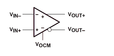
Figure 1 Standard Differential Amplifier
New differential amplifierDifferential amplifiers have several advantages. The first is anti-noise capability, which was mentioned in the introduction of differential signals. The second advantage is the addition of a differential output voltage swing (see Figure 2). The reason for this is not complicated. The two voltages at the output are inverted, and the difference is of course twice that of the single-ended output. The third advantage is the reduction of even-order signal distortion. To explain this, we represent the output voltage as a multi-order function at the input.
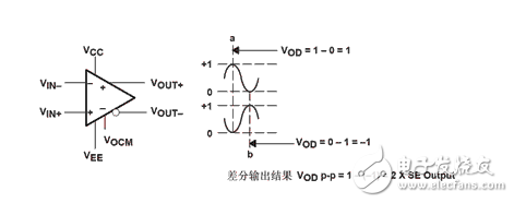
Figure 2 differential output voltage pendulum
Vout+ = k1Vin + k2Vin2 + k3Vin3 + ... , (1)
Vout- = k1(-Vin) + k2(-Vin)2 + k3(-Vin)3+... (2)
Vod = Vout-Vout-=2k1Vin + 2k3Vin3 + ... (3)
As can be seen from equation (3), the even orders are eliminated.
In order to adapt to the development of the market, various companies have introduced their own differential amplifier products, such as ADI's AD4937/4938, TI's THS4520, MAXIM's MAX4198/MAX4199, and Linear's LTC6400. Thanks to advances in technology, the technical parameters of these products have reached a very high level. Taking AD4937 as an example, the input voltage noise is 2.2nV/√Hz; the 1.6GHz-3dB bandwidth, the gain G=1; the slew rate is 5000V/μS; the 0.1dB gain flatness bandwidth at 125MHz; DC to 100MHz ADC.
Magnetic Buzzer Self-drive Type
The magnetic buzzers (Self-drive Type) offer optimal
sound and performance for all types of audible alert and identification. Our
magnetic Buzzer solutions are offered with various mounting options. We also
provide you with a washable version for your preferred soldering method. Our magnetic buzzers, also known
as indicators, are designed with an internal drive circuit for easy application
integration. During operation, current is driven through a voice coil to
produce a magnetic field. When a voltage is applied, the coil generates a
magnetic field and then allows the diaphragm to vibrate and produce sound. This
buzzer type has a low operating voltage ranging from 1.5 – 12V+. Our magnetic
buzzers are desirable for applications requiring a lower sound pressure level
(SPL) and frequency.
Passive Buzzer,Dc Magnetic Buzzer,Electro Magnetic Buzzer,Magnetic Buzzer Self Drive Type
Jiangsu Huawha Electronices Co.,Ltd , https://www.hnbuzzer.com