We do not expect a 5V low-power op amp to produce a sine wave with -100dBc distortion. Nonetheless, the bandpass filter using the LTC6258 can still be combined with an easy-to-use, low-power oscillator to produce a practical sine wave at low cost, low voltage, and very low power consumption.
Why is the LTC6258 so "magical"?
Active filter
The bandpass filter shown in Figure 1 is AC coupled to one input. Therefore, the LTC6258 input does not impose a burden on the previous circuit stage to generate a specific absolute common-mode voltage. A simple resistor divider consisting of RA1 and RA2 is responsible for biasing the LTC6258 bandpass filter. Defining the op amp input at a fixed voltage helps reduce the distortion that can occur due to common mode movement.
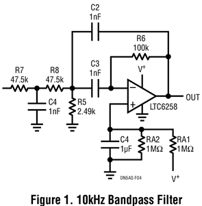
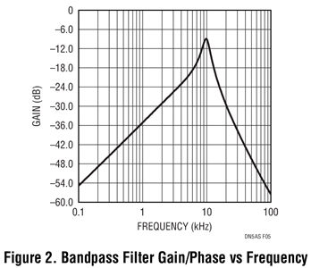
The center frequency of this filter is 10 kHz. The exact resistance and capacitance values ​​can be fine-tuned up or down, depending on whether the most important is to achieve the lowest resistance noise or the smallest total supply current. This embodiment optimizes for low power consumption by reducing the current in the feedback loop. Capacitors C2 and C3 are initially 4.7nF or higher and use lower resistor values. Finally, 1nF capacitors and higher value resistors are used for lower power consumption.
In addition to power consumption, the second and equally important aspect of the feedback impedance is the load on the rail-to-rail output stage of the op amp. Heavier loads (eg, impedances between 1K and 10K) significantly reduce the open-loop gain, which in turn affects the accuracy of the bandpass filter. The product manual recommends reducing the AVOL by a factor of 5 (impedance from 100kΩ to 10kΩ). It may be feasible to use lower C2 and C3, but in this way R6 will become larger, causing more noise at the output.
The target Q of the bandpass filter is moderate, approximately 3. A modest Q value (rather than a high Q value) allows the use of capacitors with 5% accuracy. Higher Q values ​​will require the use of more accurate capacitors, and it is highly likely that higher open loop gains (at 10 kHz) than those available with feedback impedance loads are required. Of course, compared to higher Q values, moderate Q values ​​will produce less harmonic attenuation.
A low power sine wave generator can be obtained by driving a square wave into a bandpass filter. A complete circuit schematic is shown in Figure 3. The LTC6906 micropower resistor set oscillator can be easily configured as a 10kHz square wave and can drive a relatively gentle load in the bandpass filter input resistor. The LTC6906 has a supply current of 32.4 μA at 10 kHz.
Figure 4 shows the LTC6906 output and bandpass filter output. The sine wave's HD2 is –46.1dBc and HD3 is –32.6dBc. The outputs are 1.34VP-P to 1.44VP-P, with precise levels due to limited op amp open-loop gain (at 10 kHz). When using a 3V supply rail, the total current consumption is less than 55μA.
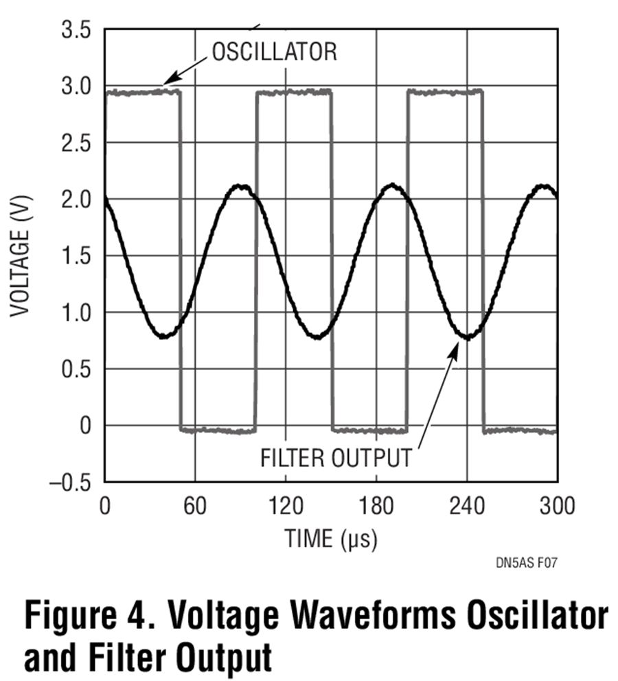
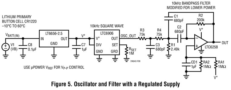
Figure 5 shows optional enhancements. A low-power reference leverages the capabilities of the LTC6906 and LTC6258 to operate at very low power supplies. The reference provides 2.5V from a battery input. A fixed 2.5V power supply stabilizes the output voltage swing in the presence of a change in input voltage. In addition, the lower filter capacitance and higher resistance further reduce the LTC6258's load, which reduces power consumption and improves filter accuracy.
The LTC6258/LTC6259/LTC6260 series (single, dual, and quad) provide a 1.3MHz gain bandwidth at low supply currents of 20μA with 400μV maximum offset voltage and rail-to-rail inputs and outputs. Combined with a 1.8V to 5.25V supply, these op amps enable applications that require superior performance at low cost and low voltage.
M8 distribution box is a kind of industrial connector. It is a device that converts a power supply or data into a shunt and outputs multiple current or data signals. General M8 distribution box refers to the line socket for M8 or M12 specifications of the distribution box. The difference between it and the ordinary socket is that the power output of the ordinary socket is only positive and negative two levels, or there is a ground wire, while the industrial distribution box, the power output is needle I/O port.
M8 Distribution Box,D-Sub Input Distribution Box,M8 distribution box 4 way, M8 Junction Box 8 port,M8 distribution box 12 way
Kunshan SVL Electric Co.,Ltd , https://www.svlelectric.com