The basic process of circuit design is generally this: demand analysis - component selection - schematic design - PCB design - welding debugging.
â–¼Requirement Analysis:
Here, it is mainly to determine which modules, peripherals or interfaces are needed for the car. First of all, the STM32 minimum system is a must, which is the core of the car control. Then the two wheels of the car require two H-bridge drive and encoder interfaces. The gyroscope is required to sense the attitude of the car (including inclination, steering angle, angular velocity, etc.). Need some peripherals for debugging and indication (buzzer, LED, etc.). A power circuit is required to power the system. The battery voltage acquisition circuit is needed to collect the battery voltage in real time and do a low voltage alarm to prevent the battery from being over-discharged. Need to download the serial port for interface and debugging. Basically, it is based on what you want to achieve, and then determine which circuits are needed.
â–¼Component selection:
Select components for each part of the circuit that is needed. Generally speaking, which type of chip is selected and what package is used. For some special circuits, even passive components such as resistors and capacitors need to be carefully selected. The circuit does not require some high-precision or high-speed circuit parts, so the following mainly introduces how to select the main chips of each circuit part.
1. Minimal system: Considering that the main control board of the car can be used as the basic circuit for four-axis or other more advanced robots in the future, the main control selects STM32F405RGT6. This main control is M3 core, and the main frequency can reach 168M. A wealth of peripheral resources can be used, the performance is very strong, very suitable for future development and expansion.
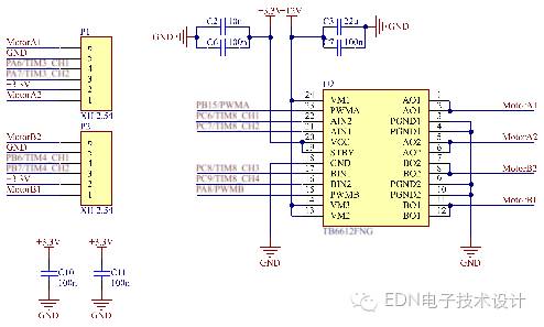
2. Motor drive: The two wheel motors of the car require two H-bridge drives. The choice of drive is closely related to the parameters of the motor. The normal working current of the motor I chose is 360mA, and considering that the car will not be gambling under normal conditions, and in order to minimize the area of ​​the PCB, I chose Toshiba's motor driver chip TB6612, which has Two integrated H-bridges can drive two motors at the same time. Each H-bridge can continuously output 1.2A current. The PWM frequency can be up to 100kHz. The chip's supply voltage can be up to 15V. It is suitable for power supply with 3S battery and chip package. Very small, saving PCB area.
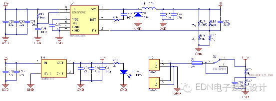
3. Power circuit: Mainly consider the input voltage, output voltage, output current and so on. The car battery uses a 3S lithium polymer battery, the discharge rate is 25C, and it can be used for four axes later. The full voltage of the battery is about 12.6V, and the circuit needs 5V and 3.3V power supply. Therefore, it is necessary to select two models to step down the 12V voltage to 5V, and then step down the 5V to 3.3V. The 12V-5V chip can choose MPS DCDC step-down chip MP2482. The chip supports up to 5A current output, maximum 28V voltage input, and adjustable voltage output of 0.8 to 25V. The 5V-3.3V uses the common AMS1117-3.3.
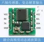
4. Gyro: The MPU6050 module is selected. The module comes with a software filtering algorithm. The serial port outputs data externally. In the case of 115200 baud rate, 100 frames of data can be output per second.
â–¼ schematic design:
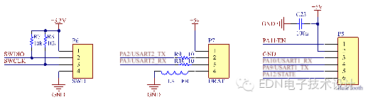
1. Minimum system: including stm32f405rgt6, crystal oscillator circuit, reset circuit. R2 and R3 are used to configure the boot mode. C9 and C12 are the filter capacitors of the internal power conversion part of the microcontroller. The minimum system is basically the same, and there is generally nothing wrong with the usual circuit design. The decoupling capacitors of several capacitive chips, note that the analog voltage, analog ground and digital power, and digital ground are separated by magnetic beads to prevent the high frequency noise of the digital circuit from affecting the accuracy of the analog circuit.
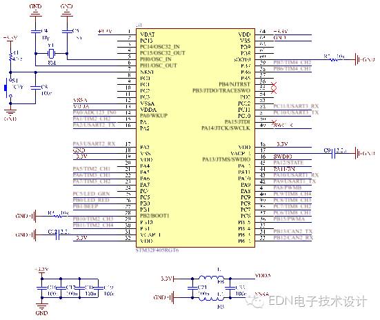
2. Power circuit: R22 and R23 divide the battery voltage to 1.2V, connect it to the ADC pin inside the microcontroller, monitor the battery voltage, and prevent over-discharge.
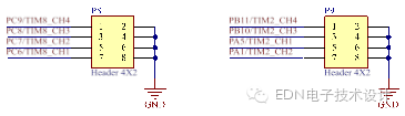
3. Motor drive and encoder circuit: Basically, it is designed according to the reference circuit on the chip datasheet. Pay attention to the decoupling of the power supply. Because the voltage of the motor is high and the current is large, it is easy to affect other circuits through the power network.
4. Gyro: integrated module, nothing to say, just connect the pin to the microcontroller, simply on the power supply pin and a capacitor to do a power decoupling (do not do it, because the module has already done ).

5.CAN communication: CAN communication is not used on the car, but CAN communication is widely used in current robot design. And we have to do the car to learn things, plus tune, learn more knowledge, why not? The chip for CAN communication is Philips' TJA1050, which is a CAN transceiver with integrated CAN controller inside stm32. R4 is an impedance-matched resistor. There are only two nodes in the entire CAN communication network that solder this resistor. The resistance is 120 ohms. Now I have not yet thoroughly studied the knowledge related to CAN communication, and will study it in detail later when debugging CAN communication. (^.^)

6. Debug circuit and other interfaces: SWD download interface, USART debug serial port, Bluetooth interface (depending on the selected Bluetooth module, determine the use of different pins of the interface, such as enable pin, status input pin, etc., when writing Bluetooth later) description). Buzzer and bi-color LED lights are used for debugging and indication. In addition, several timer pins have been introduced, which can be reserved for expansion.

â–¼PCB design:
I won't go into details. The precautions mainly include power supply decoupling (for details, please refer to my previous blog about power supply decoupling), line width control (large current traces should be as wide as possible), and switching power supply layout and wiring (generally, remember three main points) Just fine: First, the signal of the SW of the chip is a high-voltage, high-frequency switching signal, which will cause serious interference to other circuits, and should be kept away from sensitive circuits as much as possible. Second, the feedback network is a very sensitive network, try to avoid Interference. Third, the current of the power supply is large, pay attention to the line width and the number of vias, aperture, etc., to ensure the ability to pass such a large current. Note these three points, the integrated DCDC circuit is generally no problem).
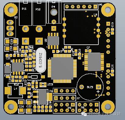
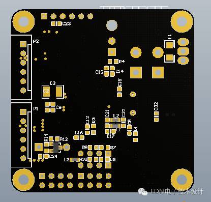
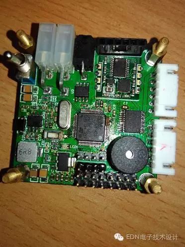
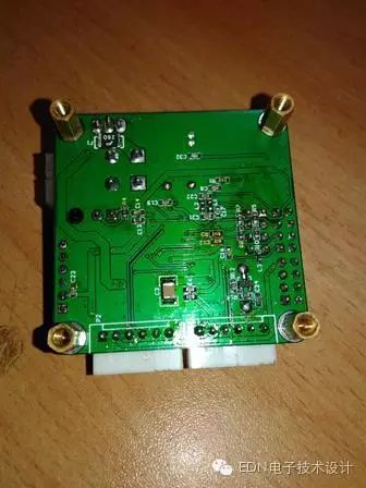
Here is a 3D rendering of the front and back sides of the board:
â–¼ welding debugging: not much to say, usually practice more hands, 0603 QFP these packaged components can be easily done. When soldering, first solder the power supply part. If there is no problem with the power supply test, solder other parts. Otherwise, if there is a problem with the power supply, the whole board is completely white soldered. . Paste a physical map that has been welded and debugged.
Just write this first. The above is awkward, and there is no such thing as a tall technology. It is almost the basic knowledge required for hardware circuit design. I just hope that I will compare the process of designing this balanced car board with a systematic and popular introduction. I can only learn from my experience in this practice. I have not touched this aspect of my friends and can use it as a reference. , quick start. At the same time, I hope that experts and experts can give more advice.
Solar On and Off Grid Inverter
Grid Tie Inverter,Solar Pump Inverter,On Grid Solar Inverter,On And Off Grid Inverter
Jinan Xinyuhua Energy Technology Co.,Ltd , https://www.xyhenergy.com