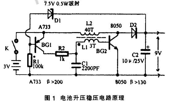
Brief description of the principle: The circuit is shown in Figure 1. When the power switch K is closed, BG1 is connected to the negative pole of the power supply due to R1, and provides positive current to the e and b poles of BG1 to be turned on. The current after conduction is applied to the b pole of BG2 via R2 and L1, and BG2 is also turned on. At the same time, L2 connected to the c-pole of BG2 is induced to L1, and BG2 is intermittently oscillated. The pulsed alternating voltage formed by the oscillation is rectified by D2, and a DC voltage is formed on the filter capacitor C2. When the DC voltage reaches the D1 regulation value (7.5V), D1 is turned on, giving
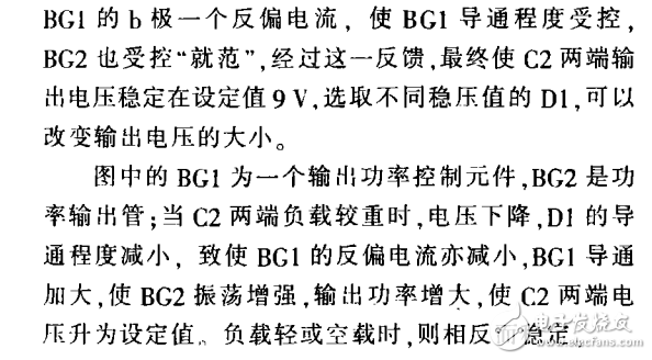
The magnetic ring in the circuit of the above figure a uses φ8mm~φlOmm, which can be removed from the scrapped electronic ballast. L1 is wound around 42 turns with an enamel of 0.27 mm. L2 is also wound around 3åŒ~4åŒ. BG1 and BG3 are NPN type silicon small power tubes (such as C945, 9014), B≥180; BG2 selects C8550 (PNP, 30V, 1A, 0.6W), and there is no recommended replacement in this circuit; The components are commonly used, and the parameters can be marked in the circuit diagram.
Connect all components as shown in the figure (you can not use the circuit board). If the current is static (without load) and the current is greater than ImA, the circuit may not oscillate. In this case, you can exchange Ll or L2 at both ends. In normal operation, the quiescent current should be less than 0.7mA (generally 0.4mA~0.5mA). If the output voltage does not meet the requirements at both ends of C3, it can be completed by replacing the voltage regulator D3. The C3 capacity should not be greater than lOμF. Otherwise, the circuit may not start to oscillate and the BG2 will become saturated, resulting in a large quiescent current without output failure. In order to ensure a high boost conversion efficiency, R1 should not be less than 220kΩ. When the circuit is normally loaded (500-4 type RxlOk block 85kΩ current limiting resistor and the positive and negative test leads touch OΩ), the working current is only 1.8mA ( 1.2V rechargeable battery).
The circuit of Figure b above is suitable for the production parameters of the digital meter.

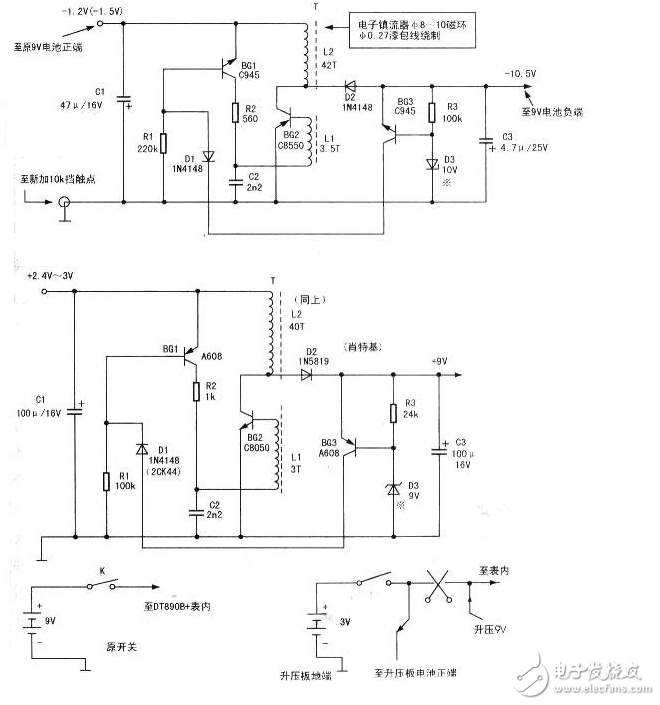
Adding method 500-4 type multimeter measuring potential resistance part of the circuit see the right picture (used in the 500 series), the table inside the gear switch part of the figure below.
In the RxlOk block of the Model 500 series multimeter, the switch contacts are vacant (no static contacts are provided), but some of them have terminal posts here, which are blocked from RxlOk. After observing and consulting the relevant circuit, it is not difficult to find that the moving contact of the electric block is just the positive electrode of the battery in the table. At this time, a contact can be added in the original RxlOk stop position, and the 1.5V positive electrode is supplied to the battery boost circuit. Remove the soldering piece with the terminal at the original RxlOk stop position, and connect the connected wire to the original circuit. If the position has other static contacts (generally under the insulating plate), carefully rivet the contact.锉 并 并 ( 自制 自制 自制 自制 自制 自制 自制 自制 自制 自制 自制 自制 自制 自制 自制 自制 自制 自制 自制 自制 自制 自制 自制 自制 自制 自制 自制 自制 自制 自制 自制 自制 自制 自制 自制 自制 自制 自制 自制 自制 自制 自制 自制 自制 自制 自制 自制 自制 自制 自制 自制 自制 自制 自制 自制Long rivet positioning. Then place the contact piece removed from the previous table below the position (depending on the table), use the super glue to stick the two contact pieces together (note: the upper and lower contacts are not connected to each other), touch down The point is connected to the original circuit. Add a wire to the boost circuit +1.5V input terminal in the new RxlOk stop contact (upper contact), and the positive terminal of the original 9V battery column in the (ground) boost circuit -1.5V termination table, boost circuit output -10.5V is connected to the negative end of the original 9V battery column, and the entire booster board can be installed in the 9V battery compartment. At this point, the installation is completed, and it becomes a single-cell battery-powered multimeter with no 9V battery.
The boost circuit is shown in the figure. It is a self-excited oscillating boost circuit. If you want enough voltage and current, it will not be reached in an instant, and it takes tens of seconds of boost waiting time. In order to obtain sufficient stable voltage and current, no voltage drop is generated during the detection, and the storage capacitor will bear the power consumption compensation (the capacity of which is most large enough). For this reason, the oscillation circuit should be mechanically switched on the switch, and should not be used. Electronic switch, otherwise, the boost voltage load does not tend, the maximum value is not accurate, the error is large; because the 5th battery, zinc manganese 1.5v, nickel cadmium / nickel hydrogen 1.2v, the voltage is very low, save There is less electric arrogance, so it is not appropriate to use electrical power to switch. The mechanical switch uses a miniature long-handle self-locking button switch. If there is only a short handle on the hand, a long handle can be welded with a plastic welding torch. I use the discarded universal universal short-handle button self-locking switch and welded long handle to make the effect very good.
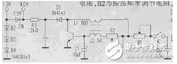
In the circuit diagram, after the resistance values ​​of R1 and R2 are adjusted, the fixed value resistors are used instead. R1 is the current regulating resistor and R2 is the oscillation frequency adjusting resistor. R3 is a voltage divider current limiting resistor.
Glass Display,High Transparency Led Glass Digital Screen,Glass Window Led Advertising Display,High Level Outdoor Glass Led Display
Kindwin Technology (H.K.) Limited , https://www.ktl-led.com