The DS18B20 is a single-bus programmable resolution digital thermometer. The details can be found in the Chinese and English datasheets. I won't go into details.
The temperature sensor that I have been exposed to very early, I believe that everyone who has studied embedded development has used it. I am driving the DS18B20 on the STM32F4. Some small cautions are:
DS18B20 control flowAccording to the DS18B20 communication protocol, the DS18B20 can only be used as a slave, and the microcontroller system as the master. The microcontroller must control the DS18B20 to complete a temperature conversion through three steps: reset, send the ROM command, and send the RAM command. The above three steps are performed each time the DS18B20 is operated.
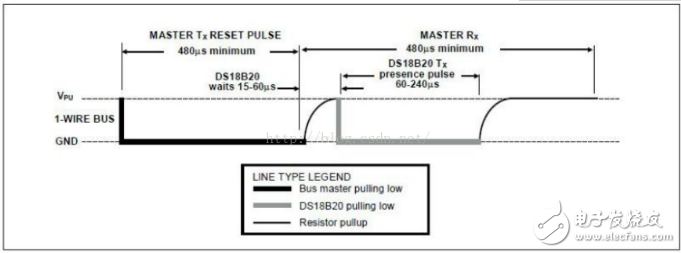
The reset process is as follows: the MCU pulls the data line low for at least 480uS, then releases the data line, waits for 15-60uS to let the DS18B20 receive the signal, and after receiving the signal, the DS18B20 will pull the data line low by 60-240uS, and the host detects that the data line is pulled. After the low flag is reset successfully;
Send ROM command: The ROM command indicates that the host addresses all DS18B20s connected to the system to determine which DS18B20 is to be operated, or to read the ROM serial number of a DS18B20.
Send RAM instruction: The RAM instruction is used by the microcontroller to operate the internal RAM of the DS18B20, such as reading the value of the register or setting the value of the register.
Please refer to the DS18B20 data sheet for specific RAM and RAM instructions. The following is a brief introduction:
1. ROM operation command: DS18B20 adopts one-line communication interface. Because of the one-line communication interface, the ROM setting must be completed first, otherwise the memory and control functions will not be available. Once the bus detects the presence of a slave device, it can issue a device ROM operation command. All ROM operation instructions are 8-bit long and provide the following functional commands:
1) Read ROM (execution code 0X33H): When there is only one node (device) on the bus, read the 64-bit serial number of this node. This instruction cannot be used if there is more than one node on the bus.
2) ROM match (execution code 0X55H): This command is followed by a 64-bit ROM serial number. Only the DS18B20 with the same serial number on the bus will react. This command is used to select a DS18B20 and then perform the DS18B20. Read and write operations.
3) Search ROM (Command Code 0XF0H): Used to determine the number of DS18B20s connected to the bus and identify all 64-bit ROM serial numbers. When the system starts working, the bus master may not know the number of devices on the bus or know its 64-bit ROM serial number. The search command is used to identify all 64-bit ROM serial numbers connected to the bus.
4) Skip ROM (execution code 0XCCH): This instruction is only suitable for only one node on the bus; this command directly accesses the RAM by allowing the bus master to provide a 64-bit ROM serial number to save operating time.
5) Alarm check (execution code 0XECH): This command is basically the same as the search ROM command. The difference is that only the DS18B20 whose temperature exceeds the set upper or lower limit will respond. As soon as the DS18B20 is powered up, the alarm condition remains set until another temperature measurement shows a non-alarm value, or the TH or TL setting is changed so that the measured value is once again within the allowable range. Triggers stored in the EEPROM are used for alarms.
RAM instructionThe DS18B20 has six RAM commands:
1) Temperature conversion (execution code 0X44H): The DS18B20 is started for temperature conversion, and the result is stored in the internal RAM.
2) Read register (execution code 0XBEH): Read the contents of the scratchpad 9 bytes, this instruction starts from the first byte (byte 0) of the RAM, up to nine bytes (byte 8 , CRC value) is read. If it is not necessary to read the contents of all bytes, the host can issue a reset signal at any time to abort the read operation.
3) Write the scratchpad (execution code 0X4EH): Write the upper and lower limit temperature alarm value and configuration data to the 2, 3, and 4 bytes of the RAM. This command is followed by the data required to enter these three bytes.
4) Copy the scratchpad (execution code 0X48H): Copy the 2, 3, and 4 bytes of the scratchpad to the EEPROM for power-down save.
5) Re-adjust E2RAM (execution code 0XB8H): Restore the upper and lower temperature limits and configuration bytes in EEROM to 2, 3, and 4 bytes of RAM. After using the above power, restore the previously saved alarm value and configuration byte.
6) Read power supply mode (execution code 0XB4H): Start the signal sent by the DS18B20 to the main CPU. For the time slice of the first readout data sent after the command is sent to the DS18B20, the device will give a signal indicating its power mode. “0†indicates parasitic power supply. “1†indicates external power supply.
1. Initialization timing should pay attention to, I personally test, in the MCU control single bus is low level 240us (requires at least 480us in the data manual) to release the bus, wait for 60us can detect the DS18B20 return low single bus signal Here, you should pay attention to at least 120us waiting here, otherwise the temperature sensor may not work properly.
2. Beginners need to pay attention to timing. For the operation of DS18B20, three steps must be taken: initialization, ROM command (mostly skip instruction 0xCC), DS18B20 function command. Re-emphasize that each of these operations must go through these three steps, and you can read the code to deepen your understanding.
3. When reading the DS18B20, pay attention to the order. The DS18B20 sends the low bit first, and should pay attention when reading the byte.
4. Beginners should try to implement the 8-bit serial number (28H) of the DS18B20 internal ROM, and the 48-bit unique serial number to read, and modify the over-temperature and low-temperature alarm values ​​of the internal EEPROM of the temperature sensor.
RandM Plus Disposable Vape Features:
0/2/3/5% Nicotine Salt.
3.2ML of E-liquid.
800 Puffs per Device.
Draw-Activated Firing Mechanism.
10 Flavors Available.
Disposable Device (Non-Rechargeable&Non-Refillable)
10pcs in a display box.
400pcs in a carton.
Flavors Available:
1.Blue Razz Ice
2.Mixed Berries
3.Lush Ice
4.Banana Milk
5.Cool Mint
6.Rainbow Candy
7.Gummy Bear
8.Aloe Grape
9.Strawberry Watermelon
10.Strawberry banana
Products Details
1 x RandM Plus Disposable Vape 800 Puffs
RandM Plus,Plus 800 Puffs Vape,RandMPlus 800 Puffs
Shenzhen Kester Technology Co., Ltd , https://www.kesterpuff.com