No matter what kind of work you design, the buttons are always indispensable. Do you know the buttons?
The switch used in the usual button is a mechanical elastic switch. When the mechanical contact is opened and closed, due to the elastic action of the mechanical contact, a push button switch does not immediately turn on stably when closed, and does not turn off when disconnected. The child is disconnected. Therefore, there are a series of jitters at the moment of closing and breaking, and the measure for not generating this phenomenon is the button debounce.
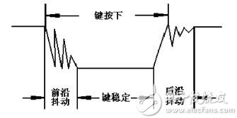
figure 1
Jitter time
The length of the jitter is determined by the mechanical characteristics of the button, typically 5ms to 10ms. This is a very important time parameter and is used in many situations.
The length of the button's stable closing time is determined by the operator's button action, usually from a few tenths of a second to a few seconds. You can test it with an oscilloscope. Key jitter causes a key to be misread multiple times. To ensure that the CPU only performs one processing of the key closure, the key jitter must be removed. The state of the key is read when the key is closed, and it must be determined that the key release is stable before processing.
Here are two ways to debounce:
First, hardware debounce:
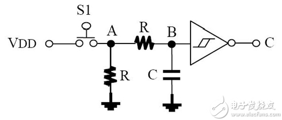
Button anti-shake circuit control circuit
The circuit using the RC integration circuit to achieve clutter filtering and waveform trimming is shown (Figure 1).
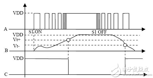
At the moment of S1 ON, due to the contact bounce, the voltage at point A will exhibit a high-speed intermittent phenomenon, and then S1 OFF, as shown in detail in Figure 2, however, since the voltage across the capacitor needs to be passed through the resistor. Slowly charging will rise, causing the B point potential to rise slowly. S1 OFF is also the case, the capacitor voltage is discharged through R, so that the voltage at point B drops slowly. This change, after trimming in reverse with Schmitt, yields a standard negative pulse output, as shown by the waveform point C.
With other types of triggers, the latch can also achieve debounce.
Second, the software is debounced:
The effect of eliminating jitter is achieved by software delay of 10ms, without text description.
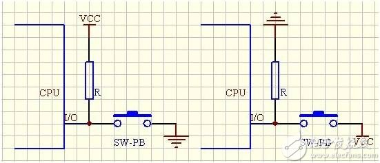
Third, the button circuit:
Independent button
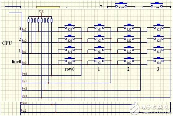
Matrix button
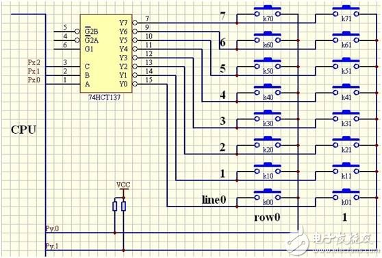
Decode button
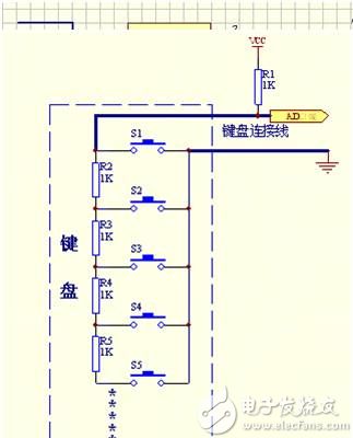
AD analog button
Lock button
Absolute rotary Encoder measure actual position by generating unique digital codes or bits (instead of pulses) that represent the encoder`s actual position. Single turn absolute encoders output codes that are repeated every full revolution and do not output data to indicate how many revolutions have been made. Multi-turn absolute encoders output a unique code for each shaft position through every rotation, up to 4096 revolutions. Unlike incremental encoders, absolute encoders will retain correct position even if power fails without homing at startup.
Absolute Encoder,Through Hollow Encoder,Absolute Encoder 13 Bit,14 Bit Optical Rotary Encoder
Jilin Lander Intelligent Technology Co., Ltd , https://www.jilinlandermotor.com