It is understood that in 2009 the domestic automobile anti-theft system output reached more than 30 million sets. Now Xinda Driving School Xiaobian will tell you about the specific situation of the design and implementation of the single-chip car anti-theft alarm system. In terms of market sales, domestic market sales increased by 20%~30% per year. According to experts' prediction, the total market demand in 2011 exceeded 11.2 million sets; another major sales channel of automobile anti-theft system is export, 2010 The export volume reached 16 million sets, and the further development of the future auto market will bring double the growth space for the car alarm market. Commonly used car anti-theft systems can be divided into four categories according to their structure: mechanical anti-theft system, electronic anti-theft system, chip-type anti-theft system and network anti-theft system.
The main problem is that the mechanical anti-theft device is difficult to resist the theft of heavy tools such as shovel, hacksaw and strong shear; the electronic anti-theft alarm device utilizes electronic technology, which overcomes the shortcomings of the mechanical anti-theft device, but is easy to produce. False positives; networked anti-theft systems cost more. In this paper, a car-based anti-theft alarm system based on single-chip microcomputer is introduced. Two STC89C52 single-chip microcomputers are used as the control core to realize the sound and light alarm. At the same time, the GSM module is used to call the owner's phone or notify the owner through SMS.

System block diagram shown in Figure 1, mainly consists of two single-chip control module, vibration sensor module, sound and light alarm module, remote control block, GSM, module, wireless transmitter and receiver module. The working principle is that after the vehicle owner starts the anti-theft mode, the sensor detection module in the signal acquisition system is in working state, and the sensor is placed in four positions of the four doors and the front and rear covers of the car. Once the corresponding external interference signal is detected, the anti-theft system is trigger. After the MCU control module makes a comprehensive judgment, on the one hand, an alarm sound is emitted to scare the thief; on the other hand, the GSM mobile communication network is used to send the short message to the owner's mobile phone to inform the vehicle of external invasion or theft. At the same time, the stolen car is searched and a base station search is performed on the signal of the in-vehicle communication device through the GSM mobile communication network to determine the location of the vehicle. The 51 series MCU is used as the main control unit, and the analog signal can be converted into a digital signal by the A/D signal through the sensor. When the main control module of the single-chip microcomputer detects the low-level signal, it starts the sound and light alarm circuit and the GSM alarm. The sound and light alarm circuit is composed of the high-brightness LED and the speaker. The GSM module uses the Siemens TC35I, and the GSM module sends a text message or calls the alarm to the owner.
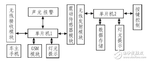
Figure 1 Block diagram of the car anti-theft system
2, system hardware design2. 1. Host control module
The main control module is composed of a button, a power-on reset circuit, and a crystal oscillator circuit. The connection is shown in Figure 2. The host control module is responsible for processing the sensor signal, sound and light alarm, the data packet of the SPI receiving transmitter module and the serial communication alarm of the TC35IGSM module.
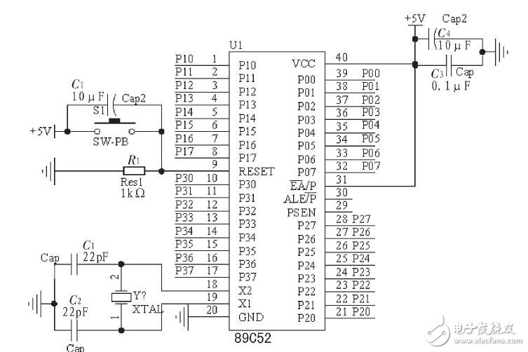
Figure 2 Host Control Module
2.2 Shock Sensor Module
The circuit of the vibration sensor module is shown in Figure 3. The working principle is that when the vibration sensor is disturbed by external vibration, the contact piece S2 becomes contact state, so that the output terminal 1 of the comparator U3A gets a low level and outputs a low power. The flat signal is sent to the P3.0 port of the single-chip microcomputer, and the MCU obtains the signal and then performs corresponding processing.
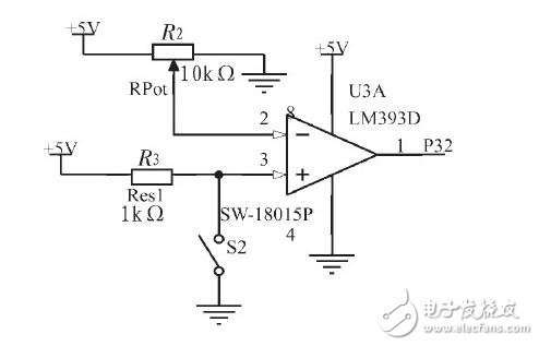
Figure 3 vibration sensor module
2.3, sound and light alarm module
The circuit of the sound and light alarm module is shown in Figure 4. The working process is output from the output port P1.6 of the MCU for 40 s high-level signal. After the ULN2003 inverter, the output low level drives the buzzer and the LED starts to flash.
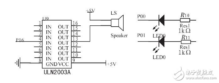
Figure 4 Sound and light alarm module
2.4, remote control module
The circuit of the remote control module is mainly composed of a single-chip circuit and a wireless transmitting module, and the remote control process thereof is shown in FIG. 5. The main control input port is the P3.2 and P3.3 ports of the MCU, and the values ​​are set to “1†and “2†respectively in the program. When the alarm is triggered by external bad interference, the owner can remotely remotely through the remote control. Pressing the button K2 is equivalent to inputting a low level to the P3.2 port, transmitting an interrupt program to the MCU through the SPI serial interface, and then transmitting a value of "1" to the wireless module, when the wireless receiving module on the alarm is obtained. When "1", it will be sent to the MCU on the alarm device, and the MCU will stop the alarm if it receives the interrupt signal. Similarly, when the K3 button is pressed, the wireless module on the alarm obtains the data and transmits it to the microcontroller for execution. Its function is set to prevent the system from being turned off.
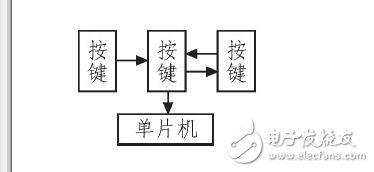
Figure 5 remote control circuit flow chart
2.5, GSM alarm module
When the vibration sensor detects a low level, the MCU communicates with the MCU through the TTL level of the serial communication circuit TXD and RXD interface, and simultaneously sends the AT command to realize the communication between the MCU and the GSM module, so that the SMS can be sent or called. The user owner realizes the burglar alarm of the car. TC35I is a new generation wireless communication GSM module launched by Siemens. It has RS232 communication interface, which can easily communicate with PC and MCU. Data, voice transmission, Short Message Service and fax in the system solution can be implemented quickly, safely and reliably. The TC35I module operates from 3.3 to 5.5 V and can operate in both 900 MHz and 1 800 MHz bands, with power consumption of 2 W (900 M) and 1 W (1800 M), respectively. The module has a rich AT command set interface that supports text and PDU mode short messages, a third set of Class 2 fax, and a 2.4 k, 4.8 k, 9.6 k non-transparent mode.
3, system software designThe system software design adopts modular design and consists of main program, initialization subroutine, interrupt service and timer T1 setting program, NRF2401 remote control transmitting program, GSM calling telephone program and stop alarm program.
3.1, the main program
The main program flow chart is shown in Figure 6. First, hardware initialization is performed to make the hardware in the ready state. The nrf24110 wireless receiving module is configured to receive mode. After initialization, the power supply is in a low power consumption state. When the system detects the vibration sensor signal, it starts the sound and light alarm or GSM to make a call. Alarm, this is two alarm modes, you can press the function key to switch.
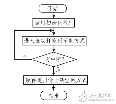
Figure 6 main program flow chart
3.2, initialization procedures
The initialization procedure is shown in Figure 7. First initialize the serial port, including selecting the serial port working mode and baud rate setting. Initialize the IO level of the MCU, configure the NRF2401 to receive mode, initialize the GSM mobile phone module, make GSM in standby state, open the total interrupt, and open the external interrupt.
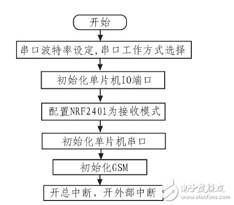
Figure 7 initialization program flow chart
3.3, external interrupt INT0 service program and timer T0 program
The external interrupt INT0 service program and timer T0 program are shown in Figure 8. The external interrupt INT0 service program mainly detects the level signal of the vibration sensor. After entering the interrupt service routine, the total interrupt and the external INT0 interrupt are turned off. If the low level is detected, the timer T0 is started, and the working mode of T0 is 16-bit counting. , timing 1 second, timing 1 second is mainly used for LED lights flashing and buzzer alarm within 1 second interval.
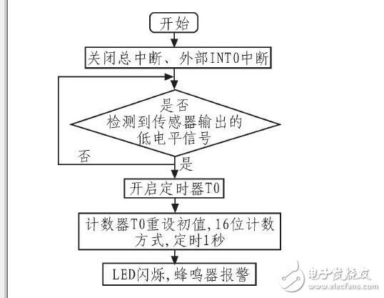
Figure 8 external interrupt INT0 service program and timer T0 program flow chart
3.4, NRF2401 remote control launch program
The NRF2401 remote control transmitter program is shown in Figure 9. The NRF2401 is configured for the transmit mode. When a button is pressed, the NRF2401 enters the interrupt mode. The NRF2401 packs the data. The microcontroller and the NRF2401 perform SPI communication, and cyclically shift the data to the NRF2401 receiver module.
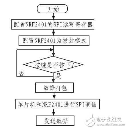
Figure 9 NRF2401 remote control transmitter flow chart
3.5, NRF2401 remote control receiving program
The NRF2401 remote control receiving program is shown in Figure 10. The NRF2410 is configured to receive the mode. The main control system and the NRF2410 perform SPI communication. When the NRF2410 receiving module receives the data, the timer stops counting, the LED light is off, and the buzzer stops beeping, communication. End.
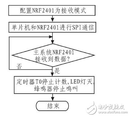
Figure 10 NRF2401 remote control receiving program flow chart
3.6, GSM call procedure
The GSM call procedure is shown in Figure 11. Initialize the serial port of the single-chip microcomputer, set the serial port working mode and baud rate, open the total interrupt and external interrupt, in order to detect the low-level signal of the sensor. If the low-level signal of the sensor is detected, the single-chip communication between the single-chip microcomputer and the GSM module is sent through the serial port. AT command, control GSM, if the MCU and GSM handshake is successful, that is, the MCU successfully sends data to GSM, GSM successfully receives the data from the MCU, but the MCU then sends ATD to make a call command to control GSM to make a call, after the owner receives the alarm call, The alarm can be processed.
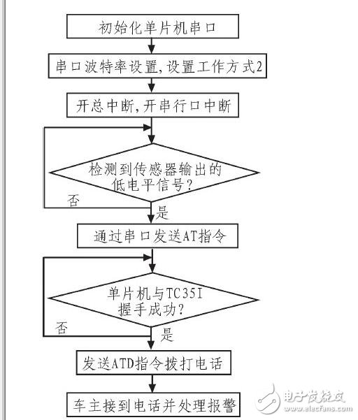
Figure 11 GSM call procedure flow chart
4 Conclusion The design and manufacture of automobile anti-theft alarm system adopts STC89C52 single-chip microcomputer as the main control chip, which can realize real-time sound and light anti-theft alarm at the same time, and notify the owner by calling the owner's phone or SMS in time. Tests show that the system can accurately start and shut down the alarm system within an open range of 0~70 m. The cost of the car burglar alarm system can be controlled within a few hundred dollars. It can be used on the 3G network by replacing the communication module, and if the camera is installed on the car, the real-time picture can be transmitted to the owner, which provides strong evidence for the future alarm.
TPU PC Phone Case,Flip Cover Leather Case,Genuine Leather Case,Best Premium Pu Leather Case
Guangzhou Jiaqi International Trade Co., Ltd , https://www.make-case.com