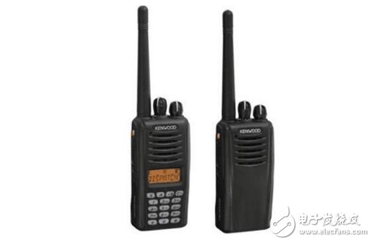
The English name of the walkie-talkie is two way radio. It is a two-way mobile communication tool. It can talk without any network support, and there is no call charge. It is suitable for relatively fixed and frequent calls. There are currently three types of walkie-talkies: analog walkie-talkies, digital walkie-talkies, and IP walkie-talkies.
How the walkie-talkie works1. Launch part:
The phase-locked loop and the voltage-controlled oscillator (VCO) generate the transmitted RF carrier signal, which is buffer amplified, stimulates the amplification, and the power amplifier generates the rated RF power. The antenna low-pass filter suppresses the harmonic components and then transmits them through the antenna. .
2. Receiving part:
The receiving portion mixes the amplified signal from the radio frequency with the first local oscillator signal from the phase locked loop frequency synthesizer circuit at the first mixer and generates a first intermediate frequency signal. The first intermediate frequency signal further cancels the adjacent channel clutter signal through the crystal filter. The filtered first intermediate frequency signal enters the intermediate frequency processing chip, and the second local oscillation signal is mixed again to generate a second intermediate frequency signal, and the second intermediate frequency signal is filtered and removed by a ceramic filter to filter out unwanted spurious signals. Generate an audio signal. The audio signal is amplified by amplifying, bandpass filter, de-emphasis, etc., into the volume control circuit and the power amplifier to amplify, drive the speaker, and get the information people need.
3. Modulation signal and modulation circuit:
The voice of a person is converted into an electrical signal of audio through a microphone
4. Signaling processing:
The CPU generates a CTCSS/CDCSS signal that is amplified and adjusted to enter the voltage controlled oscillator for modulation. The low frequency signal obtained after receiving the frequency discrimination is filtered and shaped by the bandpass filter of the amplification and sub-audio, enters the CPU, compares with the preset value, and controls the output of the audio power amplifier and the speaker. That is, if it is the same as the preset value, the speaker is turned on, and if it is different, the speaker is turned off.
The circuit is as shown. Transistor V and inductor L1, capacitors C1, C2, etc. constitute a three-point capacitor oscillating circuit, which generates a carrier frequency signal with a frequency of about 100 MHz. The set of successful discharge circuit LM386 and capacitors C8, C9, C10, C11, etc. constitute a low frequency amplifier circuit. The speaker BL is also used as a microphone. When the circuit works in the receiving state, the receiving/transmitting switch is placed in the "receiving" position, and the signal received from the antenna ANT is super-conducted by the transistor V, the inductor L1, the capacitor C1, C2 and the high-frequency choke coil L2. The regenerative detection circuit performs detection. The detected audio signal is coupled to the input end of the low frequency amplifier via capacitor C8, and amplified by capacitor C11 to drive the speaker BL to sound.
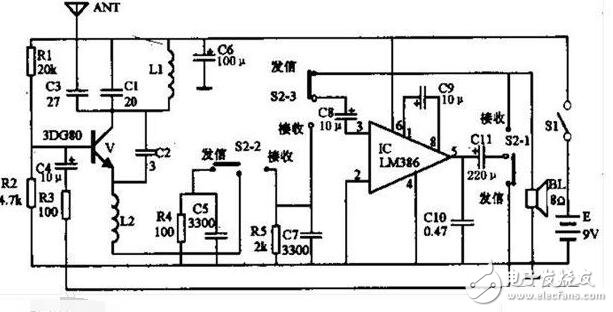
When the circuit works in the transmitting state, S2 is placed in the "send" position, and the voice is converted into an electrical signal by the speaker. After the low frequency amplification of the IC, the signal is applied to the oscillating tube by the output coupling capacitors C11, S2, R3, C4, etc. The base of V causes the bc junction capacitance of the tube to change with the change of the voice signal, and the bc junction capacitance of the tube is connected in parallel at both ends of L1, so the frequency of the oscillation circuit also changes, and the function of frequency modulation is realized. And the modulated wave is transmitted from the antenna through the capacitor C3.
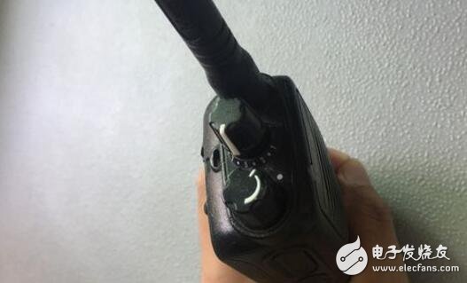
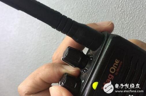
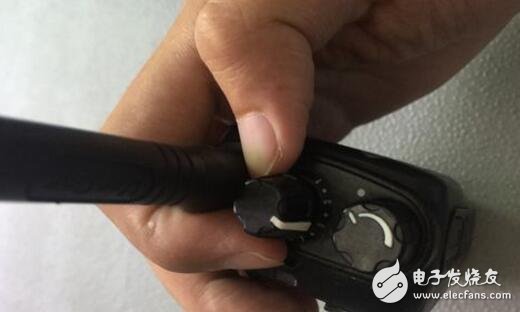
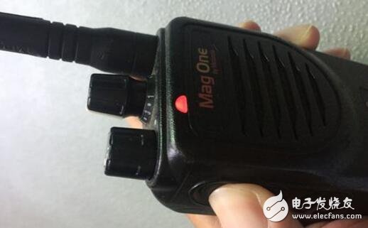
Introduction to the use of walkie-talkies1. There are three switches or knobs that are mainly needed for the walkie-talkie. The knob on the top left is a switch, and the volume can also be adjusted. The knob on the top right side is responsible for adjusting the corresponding channel; the button on the side of the walkie-talkie is the call button.
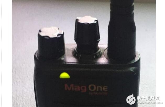
2. When turning on the machine, turn the switch knob clockwise to have a clear start sound and the indicator light will flash green once, then adjust to the appropriate volume.
3. Then adjust the walkie-talkie to the same channel. If there are frequent noises, it may conflict with other people's walkie-talkie channels, and other channels can be exchanged to avoid interference.
4. When receiving communication from others, the indicator light will flash green.
5. When you need to speak, press and hold the Talk button and start communication. When you finish speaking, release the development button.
6. If the charger is charged with the docking charger, the charger indicator will be red and not flashing for normal charging. If it is green, the charging is completed. If the indicator light flashes, it is very likely that the radio and the charger are not in good contact. Recharge the battery.

The RIMA UNG series of GEL Batteries are GEL Deep Cycle Batteries, deep cycle technology design ensures enhanced performance and a longer cycle life compared to AGM Battery. The unique plate design of the deep cycle gel battery provides a higher cycle life at increased depth of discharge.
General Future:
12-18 years design life(25℃)
Non-spillable construction
Sealed and maintenance-free
Excellent recovery from deep discharge
High density active materials plates
Longer Life and low self-discharge design
Standards:
Compliance with IEC, BS, JIS and EU standards.
UL, CE Certified
ISO45001,ISO 9001 and ISO 14001 certified production facilities
Application:
Solar and wind power system
Communication systems
Uninterruptible power supplies
Golf cars and buggies
Alarm and security system
Electric toy and wheelchairs, etc.
12 Volt Gel Batteries,Gel Batteries 12V,Gel Batteries Deep Cycle,Gel Batteries Solar
OREMA POWER CO., LTD. , http://www.oremabattery.com