Inductive wireless power transmission is becoming more and more common. Recently, many mobile phone manufacturers have announced that their new phones will support wireless charging. Most of these manufacturers use wireless charging technology based on inductive power transfer. This technology can also be used in other portable devices. In order to simplify the design of wireless charging systems, the Wireless Charging Alliance (WPC) was created and a low power standard was proposed.
This article will introduce the basic theory of wireless power transfer and outline the "Qi" standard of WPC. Finally, a low-cost discrete wireless charger solution that is compatible with the Qi standard will be introduced.
Basic theory
The basic theory of wireless power transmission based on inductive power is very simple. It is well known that an alternating electric field will generate a magnetic field, and an alternating magnetic field will also generate an electric field. On the transmitter, the direct current has been converted to alternating current and an alternating electric field is generated. At the receiver, the coil takes the power of the alternating magnetic field and converts the alternating current into direct current for the output load.
The transmitter coil and the receiver coil are separate, have large leakage inductance and a small coupling factor, so the transmission efficiency is extremely low. To improve transmission efficiency, a compensation circuit must be used. A common approach is to place a compensation capacitor at both the transmitter and receiver ends, forming a resonant circuit with the transmitter and receiver coils to improve power transfer. Figure 1 shows the topology of two compensation circuit methods. Typically, the capacitor is placed on the transmit end to form a series resonant circuit with the transmitter coil, while at the receiver end there are two types of structures with different topologies. One is a capacitor that forms a series resonant circuit with the receiver coil, and the other is a capacitor that forms a parallel resonant circuit with the receiver coil.
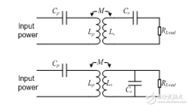
Figure 1 – Two resonant circuit topologies
The voltage transfer function is as follows,
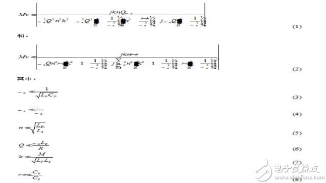
Cp and Lp are the series capacitance and inductance values ​​of the transmitter-side transmitter coil, and Cs and Ls are the series or parallel capacitance values ​​of the receiver-side receiver coil and their series inductance values. M is mutual inductance. Ω0 is the resonant frequency. Ωn is the normalized operating frequency. n is the ratio of the two coil inductances. Q is the quality factor. K is the coupling factor. α is the ratio of the transmitter series capacitor to the receiver capacitor. R is the output load.
The series resistance of the coil is not considered in Equation 2. If the circuit model is changed, as shown in Figure 2, the voltage transfer function of the series resonant circuit will be changed as shown below.
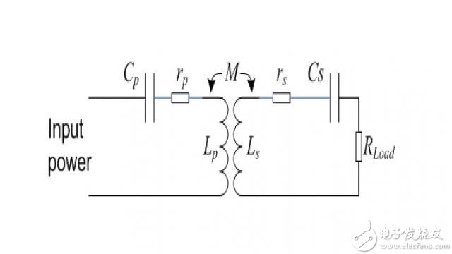
Figure 2 Series resonant circuit with inductive series resistance
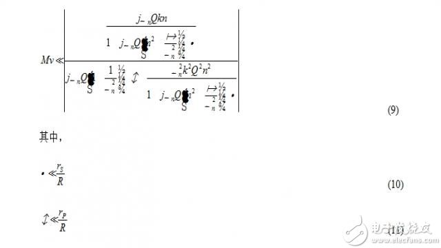
And, the equation on the parallel resonant circuit is similar.
There are some parameters that affect the wireless charger system. In wireless charger applications, series resonant circuits are used in most system receivers, so we will only discuss the following circuits.
( 1) Quality factor
In Equation 6, Q is called a figure of merit. A change in the transmitter coil or output resistance affects the Q value. In a wireless charger system, the operating point is set at the resonant frequency. The transmitter resonant frequency and the receiver resonant frequency are always the same. Therefore, the value of the voltage transfer function at the resonant frequency (ωn = 1) is of interest to us. Figure 3 illustrates the system voltage transfer function versus Q value change.
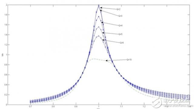
Figure 3 Voltage transfer function with different quality factors
From the figure we can see that when the Q value becomes smaller, the voltage transfer function curve of the resonance frequency point changes more obviously. In this case, the voltage transfer function is extremely sensitive to frequency and cannot easily stabilize the output. On the other hand, when the Q value becomes large, the curve of the resonance frequency changes slowly, but the voltage transfer function becomes extremely low. To achieve the same output voltage, we must apply a larger input voltage and current to the transmitter, which can significantly reduce efficiency. Therefore we need to carefully select the appropriate Q value. As usual, the range is between 4 and 6.
(2) Coupling factor.
In Equation 7, K is called a coupling factor. As we know, the transmitter produces magnetic flux. The more magnetic flux that reaches the receiver, the better the coil coupling. The coupling factor is used to measure this coupling. The coupling factor value is between 0 and 1, where 0 means that the transmitter coil and the receiver coil are independent, and 1 means they are perfectly coupled. When the coils are perfectly coupled, the magnetic flux generated by the transmitter coils is all collected by the receiver coils.

Figure 4 Voltage transfer function with different coupling factors
Figure 4 shows how the coupling factor affects the voltage transfer function curve. From this figure, it can be found that there is a k value in which the voltage transfer function reaches a peak value, which means that the maximum performance is achieved. So a well coupled coil is critical to achieving better system performance.
WPC wireless charger standard
A wireless charging alliance was created to set up a wireless power transfer standard for short-range mobile devices called "Qi." The WPC standard defines an inductive coupling operating method in a low power wireless device and a communication protocol between the power transmitter and the receiver. It also defines a maximum power of 5 W from the transmitter to the receiver and a typical distance of 5 mm between the transmitter coil and the receiver coil. The basic system schematic is shown in Figure 5. Any device that works according to the WPC standard can be used with any other WPC-compliant device. In the Qi standard V1.1, a foreign matter detection (FOD) function was added.
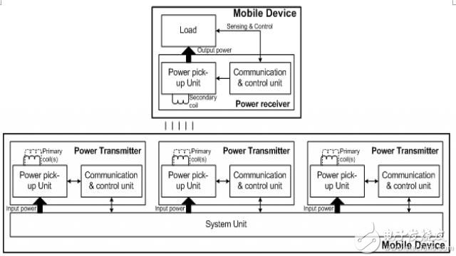
Figure 5 basic system
(1) Power transmitter
There are three types of power transmitters in the WPC standard: guided positioning, free positioning with moving coils, and free positioning with a coil matrix as shown in FIG.
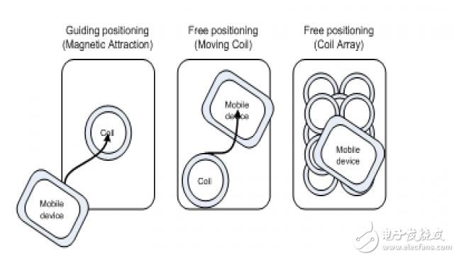
Figure 6 Three power transmitter positioning types
With guided positioning, the center of the receiver coil must be aligned with the center of the transmitter coil. Otherwise, the transmission power and transmission efficiency will be significantly reduced. Therefore, two magnets are used in the transmitter coil and the receiver coil to align and converge the magnetic lines of force.
Free positioning is a better type of transmitter because it allows the end user to easily wirelessly charge. There are two subtypes to implement this feature. One is the mobile transmitter coil and the other is the transmitter coil matrix. In the first type, when the receiver is placed on the surface of the transmitter, the transmitter aligns with the receiver coil by moving the coil and then transmits power. In the second type, the transmitter coils are formed by a matrix of coils. When the receiver is placed on the transmitter, one or more coils around the receiver coil are activated and power is delivered to the receiver.
The power transmitter has a DC or AC block, for example, a half bridge connected to the series resonant circuit. The Cp and Lp parameters and input voltage vary from transmitter to transmitter. The operating frequency of the DC to AC switch is normal at 110 KHz, and the control power may change to 205 KHz. The resonant tank is also used to optimize power transfer.
The power transmitter also has a communication block to demodulate the power transmission control information of the receiver. It is formed by a voltage or current detecting circuit.
( 2) Power receiver
Power receivers are typically portable devices with a hardware design that is more simplistic than a transmitter. It usually consists of four components: a power extraction block, a full bridge rectifier circuit, a voltage regulation block, and a communication control block.
The power extraction block is composed of a series resonant circuit including a receiver coil (Ls) and a series resonant capacitor (Cs). The resonant circuit is used to optimize power reception. The shunt capacitor provides a parallel resonant circuit for detecting the receiver.
The full bridge rectifier acts as an AC to DC circuit that converts the received wave to a regulated voltage. The voltage regulation block is a DC to DC circuit that converts the higher received voltage into the voltage required by the load. The communication control block is used to transmit power control information (such as control error packets) to the power transmitter to adjust the power transfer operating point or other state of the power transmitter.
(3) Open communication
The communication between the transmitter and the receiver defined in the WPC standard is one-way communication. The direction of communication is from the receiver to the transmitter. The power receiver adjusts the amount of power by changing its impedance (such as resistance or capacitance), which causes the transmitter coil current or coil voltage to change periodically. The transmitter can detect changes in coil current or coil voltage for demodulating communication information. This standard defines the minimum amplitude difference of the transmitter coil current amplitude, or the coil voltage between logic high and logic low. They are 15mA and 200mV respectively.
The WPC standard also defines the data format in communication. In each data transfer, a packet is transmitted. A packet consists of a preamble for bit synchronization (11 bits or more 1), a one-byte header indicating the packet type, message information (1..27 bytes), and a checksum byte. One data byte is an 11-bit serial format. This format consists of a bit start bit, eight data bits, a parity bit, and a bit stop bit. The start bit is zero. The order of the data bits begins with the least significant bit. The check digit is odd and the stop bit is one. The data bits are encoded using a differential bi-phase code with a speed of 2 Kbps. The data format is shown in Figure 7.
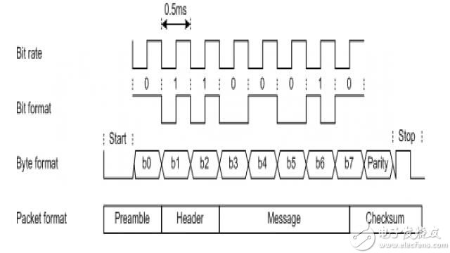
Figure 7 data format
(4) Power transmission system control
Power transfer from the power transmitter to the power receiver includes four phases defined in the WPC standard. They are the selection phase, the ping phase, the identification and configuration phase, and the power transfer phase. The relationship between the stages is shown in Figure 8.
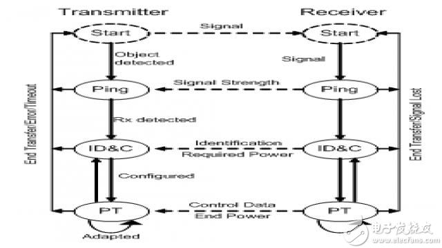
Figure 8 system control process
A. Choice
At this stage, the power transmitter detects whether it is placed on the surface or removed. Power transmitters can do this in a number of ways. If the power transmitter detects one or more objects, it should try to find these objects and distinguish between potential power receivers and foreign objects. In some cases, the power transmitter should attempt to select a primary unit and a power receiver for power transfer. If the power transmitter selects a primary unit and a power receiver, it should enter the ping phase. On the other hand, if the power transmitter does not recognize the potential power receiver or timeout, it will enter the standby mode of operation.
B. Ping
During the ping phase, the power transmitter should perform a digital ping. It checks if the potential power receiver is a power receiver or a power receiver that requires power transfer. Therefore, the power transmitter supplies power to the main coil for up to 65 ms. The power receiver must respond with load modulation during this time. Once this is done, the system goes to the next stage, the identification and configuration phase. If not completed, the system should return to the previous phase, the selection phase.
C. Identification and configuration
During the identification and configuration phase, the power transmitter should be able to identify the power receiver, and the power receiver should transmit configuration information such as the basic device identifier of the power receiver, the power receiver should provide it to its rectifier output, and the maximum power transmitter The amount of power. The power transmitter receives this information and adjusts the operating point before entering the power transfer phase. If the power transmitter is unable to correctly receive identification and configuration information from the power receiver for any reason, such as the power receiver is unable to transmit the data packet or the power transmitter is unable to demodulate the correct information, the power transmitter should return to the previous phase, the selection phase.
D. Power transmission
During the power transfer phase, the power transmitter will provide continuous power to the power receiver and adjust the power transfer operating point in response to control data received from the power receiver. During the power transfer phase, the power transmitter should monitor the power transfer parameters. If any parameter exceeds the limit, the power transfer will be aborted and returned to the selection phase. Finally, when the terminated transmission packet is received from the power receiver, the power transmitter will terminate the power transmission. For example, when the battery is fully charged, the power receiver no longer needs to charge the battery. It shall send the terminating power transmission packet information to the power transmitter to terminate the power transmission. The system will then return to the selection phase. It will remain in the first three stages until a new power receiver is placed on the power transmitter or the configuration information is changed.
Discrete wireless charger solution
We can easily design a wireless charger system with some discrete devices that are compatible with the Qi standard shown above. Figure 9 shows one of the wireless charger discrete solutions.
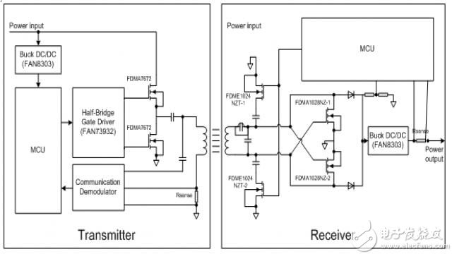
Figure 9 discrete wireless charger solution
At the transmitter end, a microcontroller unit (MCU) is used to control the entire function of the transmitter. The MCU generates a pulse width modulated (PWM) wave to drive the gate driver. The frequency and duty cycle of the PWM are controlled by the MCU. The MCU controls these two parameters based on the error control packet received from the receiver. The FAN73932 is a half-bridge gate driver that converts the received rectangular wave into two non-overlapping signals to drive the low-side and high-side MOSFETs. The DC to AC function is implemented by this device and two N-MOSFETs. The transmitter coil is driven by an AC wave. The series capacitor is used to form a series resonant circuit with the transmitter coil for better power transfer performance. Power can be transmitted in this way. The FAN8303 is a DC-DC converter that provides 5V to the MCU supply. The other part is the communication part. The capacitor is used to take the voltage from the coil and send this voltage to the MCU ADC for communication information. We can also use a sense resistor and a voltage amplifier to check the current change in the transmitter coil.
At the receiver end, the MCU is also used to control all operations of the receiver. A series resonant circuit having a receiver coil is composed of a capacitor. When the receiver coil is placed on the transmitter coil, we can get the AC voltage at the end of this series resonant circuit. The AC to DC function is implemented by a full bridge rectifier with two N-MOSFETs and two diodes. The DC voltage is taken at the output of this circuit. This voltage is stabilized by the regulator capacitor. This voltage is transmitted through the DC-DC converter (FAN8303), and a stable 5V is obtained at the output of the FAN8303 device for the MCU power supply. When the MCU is powered up, it controls two MOSFETs to communicate with the transmitter. The entire wireless system is configured in this way. The MCU will turn on the output switch after it has been properly configured. The output voltage can also be used to charge portable devices. The charging current and output voltage are monitored by the MCU to know when it is necessary to terminate charging.
In terms of software, Figure 10 shows a simplified flow chart of the wireless charger transmitter and receiver.
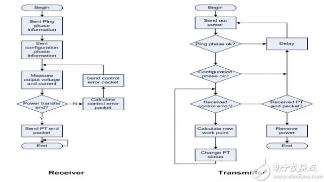
With this wireless charger system, the system can get 5W charging power with an efficiency of about 69%.
in conclusion
The wireless charger is a new application in the portable device market using old technology. The WPC Qi standard benefits the popularity of wireless chargers. With this standard, we can easily design a wireless charger system. This article only mentions several discrete devices used in the system. In addition, all the features of the Qi standard are achievable. This system is a low-cost wireless charger solution that can be widely used.
2.3 After fermentation Orange (Orange made enzyme solution navel orange), seized after the hand, breaking and other processes made of navel orange sauce.
Effects: lung, spleen shun gas, without any food additives, preservatives, is the first choice of children and senior citizens.
Companies registered capital of 35 million yuan, the end of 2014 the total assets of 48.69 million yuan, including fixed assets of 37.52 million yuan. The company's existing cooperation Orange cultivation base 7043.5 acres, the company production base is located in Jiangxi County Tech Industrial Park Chu Tan industrial area, covers an area of 120 acres, it has built a standard plant 9,000 square meters, Nissan 6000 kg Orange enzymes and other liquid enzyme products. Enzyme, known as enzyme, refers to a polymer substance having biocatalytic functionality. In the catalytic reaction system an enzyme, the reactant molecules are known as substrates, enzyme substrates by catalytic conversion to another molecule. Almost all cellular activity of enzymes involved in the process are required to improve efficiency. Similar to other non-biological catalysts, enzymes chemical reactions by lowering the activation energy to accelerate the rate of the reaction, most of the enzyme catalyzed reaction rate can be increased a million times; in fact, the enzyme is to provide an activation energy needs than another low way, so that more particles to have less than the activation energy of the reaction kinetic energy, thus speeding up the reaction rate. Enzyme as a catalyst, in itself is not consumed during the reaction, it does not affect the chemical equilibrium reactions. Positive enzyme catalysis, but also a negative catalytic effect, not only to accelerate the reaction rate, but also to reduce the reaction rate. And other non-living catalysts is different, having a high degree of specificity of enzyme, only a catalytic reaction or produce a particular specific configuration.
Enzyme Cream,Whitening Slimming Enzyme Cream ,Meal Replacement Diet Enzyme Cream ,Conditioning After Surgery Enzyme Cream
Ganzhou Green days Biochemical Technology Shower folder mechanic Co., Ltd. , https://www.cn-gangdao.com