In the past two years, motion sensing technology has begun to blossom everywhere – video consoles, smartphones, TV remotes, and personal training devices – just as we geotag mobile photos, play video games, and Cable TV set-top box for channel surfing. These things know where we are, what our goals are, where we move – up, down, around, and side. What makes this possible is a large number of new sensors that are smaller, cheaper and faster. After optimal integration, they accurately track our movements in space and time. These sensor kits (accelerometers, gyroscopes, and magnetic sensors) have amazing capabilities for tracking motion, especially when combined with today's ubiquitous GPS.
But the potential of these miniature sensors is still not fully explored, here are two simple reasons. First, extracting their data and integrating it into accurate and reliable pointing and tracking information is a more challenging algorithmic operation than most people think, often requiring a lot of manpower. Second, there is a common (but erroneous) assumption between hardware and application engineers that most sensors provide similar levels of performance, so data from sensors typically does not meet their application needs.
Motion detection sensors that are typically integrated into consumer products include 3-axis gyroscopes, 3-axis accelerometers, and 3-axis geomagnetic sensors. Each sensor has its own strengths and weaknesses in terms of motion tracking and absolute direction. Recently, sensor "fusion" is entering a wide range of consumer products, becoming an effective way to overcome the weakness of a single sensor. Sensor fusion is a sophisticated software that combines inputs from various sensors to produce a more accurate motion detection result. This kind of software usually contains complex algorithms, and if implemented correctly, can take into account hundreds of variables.
3-axis acceleration sensor
Accelerometers detect linear acceleration and gravity vectors by measuring the force on a given linear axial spring. Accelerometers are the first MEMS sensors to appear in high-volume applications and can be used to implement airbag deployment in automobiles, image stabilization in cameras, and free fall detection in notebooks. Nintendo's Wii is the first major consumer product to introduce accelerometers as user input devices that provide gesture recognition, basic motion tracking and controller positioning. Accelerometers are now very popular on smartphones and tablets for a number of reasons, including detecting device orientation, adjusting the screen from portrait to landscape, and then adjusting it back.
Accelerometers have two major drawbacks in motion tracking:
â— Accelerometers cannot establish absolute or relative heading. The 3-axis accelerometer measures the acceleration on a single acceleration axis when mounted in a fixed device. As shown in FIG. 1, when in a fixed state, the rolling and tilting angles can be calculated from the vertical gravity acceleration vector. However, the heading is obtained around the Z axis and the heading cannot be calculated from the gravity vector. Therefore, the accelerometer cannot provide heading.
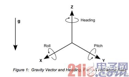
Figure 1: Gravity vector and heading, tilting and scrolling around the axis.
â— Accelerometers are too sensitive to motion and can easily cause hand shake. This is very annoying in a short time because it means that the target of the cursor or screen rendering will also be dithered. Dithering above a few minutes will result in significant cumulative direction or positional errors, especially when the accelerometer's noise is at the same order of magnitude as the jitter. The widely used low-cost consumer-grade accelerometers are much more noisy than the more expensive, larger, and more expensive industrial-grade accelerometers, as shown in Figure 2.
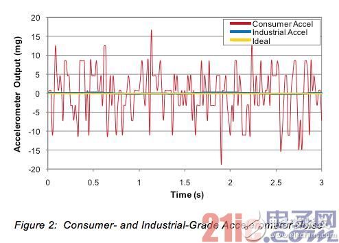
Figure 2: Consumer and industrial accelerometer noise.
3-axis gyro sensor
A gyroscope (also known as a gyroscope or an angular velocity sensor) measures the angular velocity of rotation about the axis and derives the angle of rotation about the axis by deriving. Since its introduction in the early 20th century, gyroscopes have been scaled from huge copper benchtop models to today's low-cost, low-power small MEMS chips that can be mounted under the fingernails. Consumer-grade gyroscopes were first integrated into Gyration's Air Mouse in the mid-1990s. Later, MEMS gyroscopes were widely used in Logitech's MX Air pointing devices and LG's smart TV remotes. Nintendo's Wii further enhances the gaming experience by adding gyroscopes to the Motion Plus controller. Gyroscopes have also been added to the iPhone 3GS to extend gaming potential and improve the usability of location-based services (LBS).
Just like accelerometers, gyroscopes are also inadequate:
â— The gyroscope cannot provide an absolute reference. For this reason, they are often used with accelerometers, which provide an absolute reference to the "down" by the accelerometer, which also provides an absolute reference for tilt and roll readings. Gyroscopes are often also used with geomagnetic sensors, which provide an absolute reference for heading.
◠The zero or zero offset of the gyroscope drifts with time. If not corrected in time, it will become a major source of systematic error. For example, even if the system is actually in a stopped state, the gyroscope output will report that the system is moving. For reference, the false zero offset reading is 0.07°, which is the resolution limit for consumer grade gyroscopes and will result in an error of 2.1° after 30 seconds. Figure 3 shows a typical uncorrected zero offset over a 8 minute period, while Figure 4 shows how this error translates into heading.
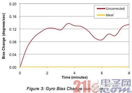
Figure 3: Gyroscope shift over time.
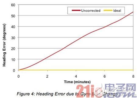
Figure 4: Heading error due to gyro zero-offset variation.
3-axis geomagnetic sensor
Geomagnetic sensors are used to measure the Earth's magnetic field and derive the heading. Geomagnetic sensors used in the past for compasses are now widely used in a wide variety of applications, including automotive compasses (in rearview mirrors), watches, radar detectors, drive shafts and robots. However, the truly widespread adoption began with the iPhone 3GS, the first smartphone in the US to include a compass and become widely available.
â— The main problem with magnetic sensors is that they measure all magnetic fields, not just the Earth's magnetic field. For example, system components such as batteries or ferrous components will interfere with the magnetic field near the sensor. These are considered to be fixed disturbances within the system and can be compensated by calibration.
• The bigger problem is that changing the local magnetic field can temporarily interfere with heading information. Metal parts on tables and chairs, opened cars, other nearby cell phones and computers, window frames, radars in buildings, etc. can interfere with readings. Compensating for these magnetic fields and other transient geomagnetic anomalies requires the development of sophisticated algorithms to effectively distinguish the Earth's magnetic field from other temporary "invasive" magnetic fields.
Sensor fusion - turning sensors into motion tracking
As mentioned earlier, accelerometers, gyroscopes, and geomagnetic sensors each have their own advantages and disadvantages. Table 1 below summarizes the main advantages and issues of each sensor in motion tracking.
As summarized in Table 1, the advantage of one sensor is often the problem of another sensor, and vice versa. By intelligently "merging" their outputs, relying on one output to adjust or replace the other, we can create a 9-axis motion tracking system that will perform much better than the simple accumulation of these devices.

Table 1: Summary of sensor advantages and issues.
Today, the 9-axis "sensor fusion" system is just beginning to gain popularity. Gyros are established as the main force of these fusion systems because of their good short-term tracking accuracy, fast response and update rates, and immunity to non-gravity acceleration. Gyro problems - 1) no absolute reference 2) severe heading drift due to zero drift - can be solved by combining accelerometers with geomagnetic sensors. Geomagnetic sensors and accelerometers provide the gyroscope with a long-term absolute reference for heading, tilting and rolling.
But the final accuracy of motion tracking is directly dependent on how good the original input from each sensor is. As we will see, not all geomagnetic sensors provide the same results.
The most widely used geomagnetic sensor in today's consumer electronics is the Hall effect sensor. The reason this sensor dominates the consumer market is small size, low price and power saving. However, such sensors are equally noisy and are susceptible to interference from other magnetic fields that would limit their ability to provide correct heading data to the gyroscope if not corrected. However, if a slightly larger size permanent magnet inductive geomagnetic sensor can be accepted, significantly improved noise and resolution performance can be achieved without sacrificing cost or power consumption. Table 2 shows the specifications for Hall effect and permanent magnet induction sensors. Note that permanent magnet inductive sensors can provide significantly lower noise and higher resolution.
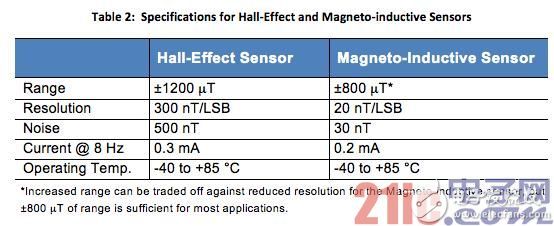
Table 2: Hall effect and permanent magnet induction sensor specifications.
The figure below shows the magnetic field readings that the geomagnetic sensor outputs when it is rotated at a fixed position on the order of 2.4 mT. In Figure 5, the sensor is rotated a full 360°, while in Figure 6, the sensor is rotated from 0° to 90°. Both figures plot test data for Hall effect sensors, permanent magnet induction sensors, and ideal sensors.
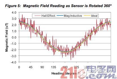
Figure 5: Magnetic field readings when the sensor is rotated 360°.
As can be seen from the figure, the noise of the Hall effect sensor is much larger than that of the permanent magnet induction sensor. This is consistent with device parameter specifications because the noise figure of the Hall effect sensor is 500nT, while the noise figure of the permanent magnet induction sensor is an order of magnitude lower, only 30nT. As shown in Figure 6, for a Hall effect sensor, a 2mT magnetic field reading can be observed in multiple directions, while a 2mT reading can represent any heading from 5° to 60°. Although oversampling can reduce this uncertainty, this very significant difference in sensor noise does lead to large measurement uncertainties. This noise difference and the uncertainty of the associated measurements will significantly affect the performance of the 9-axis sensor fusion algorithm.
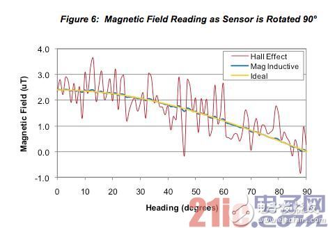
Figure 6: Magnetic field readings when the sensor is rotated 90°.
Figure 3 above shows the gyroscope bias over time, which represents the root cause of long-term heading drift. In the 9-axis sensor fusion system, the accelerometer and magnetic sensor establish a long-term benchmark for correcting the zero offset. However, the noise in the magnetic sensor readings and the type of magnetic sensor have a significant effect on the effect of the zero offset correction. Figure 7 again shows the change in bias over time, but this time an uncorrected, corrected image with a Hall effect sensor and corrected with a permanent magnet inductive sensor and an ideal output is drawn. It is worth noting that the sensor fusion algorithm used is the same for both sensors.
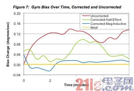
Figure 7: Gyro bias with time, including corrected and uncorrected conditions.
As is apparent from Fig. 7, the 9-axis sensor fusion system using the permanent magnet induction sensor is better than the Hall effect sensor in minimizing the variation of the bias. This improvement in bias drift is directly attributable to the noise of the permanent magnet induction sensor by an order of magnitude, because the relatively high noise of the Hall effect sensor introduces uncertainty into the sensor fusion algorithm, which in turn reduces the ability of the algorithm to control the zero offset. .
The ability of the permanent magnet inductive sensor to better control the drift of the zero offset will significantly improve the heading performance over time, as shown in Figure 8. We can see here that the long-term performance of a sensor fusion system using a Hall effect sensor is twice as effective as reducing the heading error in 8 minutes compared to an uncorrected system. However, a sensor fusion system using a permanent magnet inductive sensor can reduce the heading error by an order of magnitude compared to an uncorrected system, which is five times better than a Hall effect magnetic sensor based system.
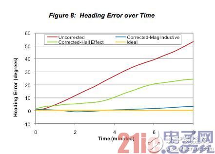
Figure 8: Heading error as a function of time.
Summary of this article
With the widespread adoption of a 9-axis sensing system using a permanent magnet inductive geomagnetic sensor instead of a Hall effect sensor, the resources required to accurately position the movement are already in place. First of all, it is necessary to understand that the accuracy and accuracy are much higher than the current motion tracking world of the "mobile proximity" system, and then it can be understood that the augmented reality in this world will be more infinitely feasible, and the game will be more intuitive to play, location-based applications. It will also be more robust.
Teaching and training meetings, classroom teaching; traditional projectors are not easy to carry. In school classrooms, due to the naughty students, projectors are not safe in the classroom and are easily damaged by students. The portability of micro projectors makes up for the teaching vacancies. In the future, teachers will give lectures. You only need to store the data in the projector to show it to students for teaching, saving the trouble of textbooks and handwriting with pens and chalks.
portable projector for teaching,portable projector education,portable classroom projector,projector for teachers
Shenzhen Happybate Trading Co.,LTD , https://www.szhappybateprojectors.com