SPI is an abbreviation for Serial Peripheral Interface. SPI is a high-speed, full-duplex, synchronous communication bus that occupies only four wires on the pins of the chip, saving the pins of the chip and saving space for the layout of the PCB. Because of this easy-to-use feature, more and more chips are now integrating this communication protocol, such as the AT91RM9200.
SPI protocol summary
The communication principle of SPI is very simple. It works in master-slave mode. This mode usually has one master device and one or more slave devices. It requires at least 4 wires, and in fact 3 can also be used (in one-way transmission). Also common to all SPI-based devices, they are SDI (data input), SDO (data output), SCLK (clock), CS (chip select).
(1) SDI – SerialData In, serial data input;
(2) SDO – SerialDataOut, serial data output;
(3) SCLK – Serial Clock, clock signal, generated by the master device;
(4) CS – Slave enable signal, controlled by the master device.
What is the I2C bus?The abbreviation of I2C--INTER-IC serial bus is the inter-chip serial transmission bus introduced by PHILIPS. It implements duplex synchronous data transmission with one serial data line (SDA) and one serial clock line (SCL). The utility model has the advantages of less interface lines, simplified control mode, small device packaging form and high communication rate. In master-slave communication, multiple I2C bus devices can be simultaneously connected to the I2C bus to identify the communication object by address.
The protocol of the I2C interface includes device address information, which can connect multiple slave devices on the same bus and exchange data and commands through response. However, the transmission rate is limited. It can reach 100Kbps in standard mode, 400Kbps in fast mode (usually 130Kbps in our development board), and 4Mbps in high-speed mode. It cannot achieve full duplex and is not suitable for transmitting a lot of data.
The I2C bus is a true multi-master bus. Multiple hosts on the bus initiate transmission and can prevent data corruption by transmission detection and arbitration.
Learn more about I2C bus timing:
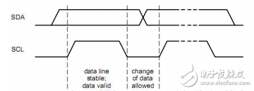
1.1 Bus data validity
The I2C bus is simplex, so there is only one flow of data at the same time, so the sampling effective clock is also single, which is the high-level sampling data of the SCL clock.
The SDA data on the I2C bus can be changed at the low level of the SCL clock, but must be stable when the clock is high, so that the master and slave devices can sample data according to the clock, as shown below:
1.2 Bus idle condition
After the device on the I2C bus releases the bus (discharge is stopped), the I2C bus goes high according to the pull-up resistor, and SDA SCL is high.
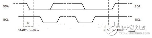
1.3 Bus data transmission start and end conditions
The high-to-low transition of SDA occurs when the I2C bus SCL is high, which marks the start condition of data transmission on the bus.
When the I2C bus SCL is high, the SDA transitions from low to high, indicating the end condition of data transmission on the bus.
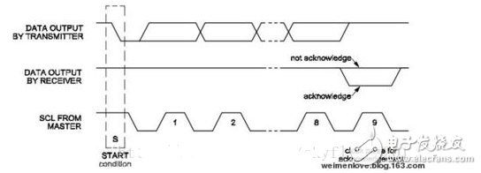
1.4 Bus data transmission sequence and ACK response
On the I2C bus, the data transmission room MSB is in front, the LSB is in the back, and from the oscilloscope, the data can be read sequentially from left to right.
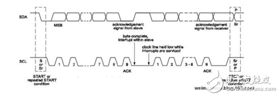
The data transmitted by the I2C bus does not accept the limit, but each time it is sent to the SDA, it must be 8 bits, and the host will release the bus after sending 8 bits. After receiving the data, the slave must pull down the SDA one clock, and the response ACK indicates that the data is successfully received. If we see the waveform on the oscilloscope is 9 bits of data each time, 8bit+1bit ack. as follows:
After the slave receives one byte of data, if it takes some time to process, it will lower the SCL, let the transmission enter the wait state, the processing is completed, release the SCL, and continue the transmission, as follows:
1.5 bus read and write timing
The data is transmitted after the start condition, sending a 7-bit slave address, followed by the 8th bit in the data direction (R/W), 0- indicating the transmitted data (write), and 1- indicating the received data (read). Data transfer is typically terminated by a stop bit (P) generated by the host. But if the host still wants to communicate on the bus, it can generate a repeated start condition (Sr) and address another slave instead of first generating a stop condition. In this transmission, there may be different combinations of read/write formats.
The I2C bus master reads and writes the slave device, which usually interacts with the slave device's registers. This can be obtained by reading the slave's datasheet. The bus write timing is as follows:
Master start + master addr|w + slave ack + master reg|w + slave ack + master data + slave ack + master restart. . Master data + slave nack + master stop
The bus read timing is as follows:
Master start + master addr|w + slave ack + master reg|w + slave ack + master restart + master addr|r + slave ack + slave data + master nack + master stop
The difference between bus read timing and write is that the read requires 2 transfers to complete a read. The first thing to write the register address to the slave device is to write to the slave device's control register or command register. The slave device will use this address internally. To address the register to be operated.
When I read our bios and kernel, I found that the implementation of the bus read timing is not the same. After the first register address is written, one sends a restart, one sends a stop, and then starts to read. Take the data, the oscilloscope grabs the waveform and finds that the read data is correct, indicating that the two timings are correct.
The read and write timing of the I2C bus is relatively fixed, and the device communication strictly follows the protocol. Therefore, the writing of the I2C bus device driver is relatively simple.
The main application of the I2C bus device is touchscreen rtc external expansion io, etc.
Privacy Hydrogel Screen Protector
The Privacy Screen Protector can display a black screen directly in front of the screen at an angle greater than 30° to effectively block the sight of people next to it, while achieving a perfect balance between black screen privacy and daytime clarity.
The Screen Protector can protect the edges and gaps of the display so that it can extend to the entire screen surface, thereby achieving maximum coverage without any exposed space.
The Self-Healing Screen Protector can provide the best protection for your phone from drops, bumps, scratches and normal wear and tear. Using an oleophobic waterproof coating can prevent sweat and grease from remaining on your fingerprints, keeping you simple all day long.
The 0.14mm thick Ultra-Thin Protective Film has a "real touch" feel and ensures fast response performance.
If you want to know more about Privacy Screen Protector products, please click the product details to view the parameters, models, pictures, prices and other information about Privacy Screen Protector.
Whether you are a group or an individual, we will try our best to provide you with accurate and comprehensive information about the Privacy Screen Protector!
Anti-peep Screen Protector, Privacy Screen Protector, Anti-spy Screen Protector, Privacy Protective Film, Privacy Hydrogel Film,Anti-peeping Screen Protector
Shenzhen Jianjiantong Technology Co., Ltd. , https://www.tpuprotector.com