Increased receiver quality and tester speed imposes more stringent requirements on signal generator performance. As spectrum becomes more crowded, the communications industry must develop new modulation techniques that increase component testing speed and performance and productivity. Therefore, more cost-effective high-quality signal source solutions are needed more than ever before.
Similar to the evolution of cars to mobile phones, the performance of signal generators continues to increase while prices are falling, and customers and consumers are continually demanding more features and performance and expecting lower prices.
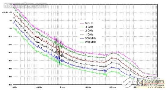
RFIC design and mobile phone production testing require signal sources to reduce phase noise and speed up frequency switching, a requirement that is often contradictory. Therefore, in general, performance optimization can only be targeted at one or the other, and rarely meet both requirements at the same time. The Aeroflex S-Series signal generator uses a characteristic frequency synthesizer design [Figure 1] to optimize both aspects of performance, with a typical phase noise of 1 GHz down to -135 dBc/Hz with a frequency switching time of less than 100 μs. Frequency offset 20-kHz [Figure 2].
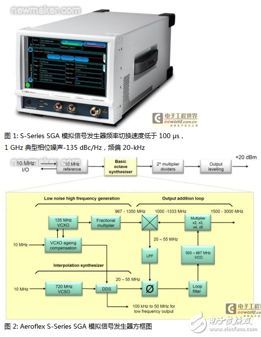
Advances in modern device technology have enabled the miniaturization and simplification of frequency synthesizer designs, which have seen significant reductions in size and cost compared to previous generations. While the signal generator is smaller and lighter, its function can be extended as the product evolves. This article focuses on the design principle of this frequency synthesizer and its impact on the output signal.
Multi-ring frequency synthesizer
The multi-ring frequency synthesizer is designed for a wider frequency range (up to 6 GHz) and extremely high frequency resolution. This special design [Figure 2] uses two phase-locked loops (PLLs). One provides a high frequency, low noise RF signal that can be stepped in the desired range in coarse step size. The Direct Digital Synthesizer (DDS) provides low frequency signals that can be interpolated for precise frequency resolution within the coarse step size. Two signals are input to the second PLL to generate the final output signal.
Low noise high frequency signal source
Although surface acoustic wave (SAW) oscillators have been the source of low noise in the 1 GHz band, the use of multiplying power VHF crystals is still the best approach. The problem is that the high-frequency crystal can reduce the noise, but it will increase the difficulty of the interpolation step. The low-frequency crystal can reduce the step size, but it will cause the noise to increase exponentially. To solve this contradiction, the 135MHz crystal and fractional multiplier are used, with a signal frequency range of 967 MHz to 1350 MHz and a step size of 22.5 MHz. Compared to a 22.5 MHz crystal, the noise floor can be improved by 16 dB with a 135 MHz crystal.
Crystal designers face conflicting requirements. Good phase noise requires high power and reduces the tuning range. The voltage-controlled crystal oscillator (VCXO) locks down to a specific frequency requiring low power and a wide tuning range due to the aging of the life cycle of the tester. The solution is to use a high-powered oscillator to reduce noise and digitally handle crystal aging. The 135MHz crystal is a 10MHz standard reference frequency phase comparison oscillator that produces accurate frequency output. The interpolation frequency synthesizer dynamically programs the frequency offset in real time.
Interpolation frequency synthesizer
The interpolated frequency synthesizer high frequency signal tuning range is 11.25 MHz to interpolate 22.5 MHz. The output loop can add or subtract frequencies, so the required range is only half of the coarse step size. Other basic features of this interpolated frequency synthesizer include:
The precision 0.01Hz synthesizer resolution range can be doubled to 6 GHz.
Offset VCXO rated frequency deviation
Apply wideband FM.
The 720MHz Voltage Control Surface Acoustic Wave Oscillator (VCSO) is a 10MHz reference frequency phase-locked oscillator used as a DDS clock. When the frequency synthesizer generates a non-modulated CW, by adding a first-level 720MHz signal, the false signal that the DDS output is already low is further reduced, and the low-frequency small deviation is filtered out. In this case, the frequency range is from 22.5 MHz to 33.75 MHz. When a frequency synthesizer is required to generate a wide-bandwidth FM signal, the nominal interpolation frequency range is changed from 33.75 MHz to 45 MHz, and the interpolated signal can be floated within ±10 MHz for wide frequency offset. The DDS output is used to directly change the frequency range from 23.75 MHz (33.75 MHz - 10 MHz) to 55 MHz (45 MHz + 10 MHz).
Output addition loop
The output loop adds the two low noise signals. The background low noise voltage controlled oscillator (VCO) is doubling the frequency range from 500 MHz to 667 MHz, reaching 1000 MHz to 1333 MHz. This signal is mixed with a low noise high frequency signal. Then, the phase difference is compared with the interpolated signal using the difference frequency. After the phase detector output is low-pass filtered, the VCO is controlled by feedback to form a complete PLL.
The octave frequency synthesizer typically uses the VCO library to cover the output range because the low noise octave tuning range is not directly accomplished. To achieve the desired tuning range, the 1/3 octave VCO can be scaled to an octave by 3, 4 or 5 times.
This multiplier uses noise lower than previously designed methods. The 1000MHz to 1333MHz signal can be doubled again to four times the VCO frequency. This signal can be used to directly generate 4x output or mix with the background VCO signal to generate 3x and 5x VCO frequencies. The adjustable bandpass filter selects the upper and lower sidebands. This method of using a multiplier plus a mixer ensures that the noise floor in the entire multiplication frequency range is lower than other methods.
Implementation and design of fast frequency switching
Achieving frequency conversion in 100 μs while maintaining low noise further presents many challenges. There are multiple analog voltages from the frequency synthesizer to the pre-tuned VCO and the frequency-tunable varactor bandpass filter. Sufficient to flexibly complete voltage tuning in a few microseconds, and keep the noise below a few nanovolts, no drift after switching is a contradictory requirement. Our approach is to rigorously screen and select low noise DACs, variable bandwidth passive filters, and filter capacitors with low dielectric absorption coefficients.
The PLL in the fractional multiplier and output summing loop uses a mixer-based phase detector. Although the noise floor is very low, their disadvantage is that the capture range is limited, which is necessary to ensure the bandwidth of the PLL loop. Traditional phase lock methods such as search oscillators are too slow for this application. When the coarse preset phase adjusts the VCO frequency to the correct range, the digital phase discrimination technology (patent pending) can be used to precisely adjust the VCO before phase locking. The FPGA compares the frequency of the two signals of the phase detector and adjusts the VCO to the correct frequency by modifying the preset voltage.
Since the PLL has a minimum bandwidth of 200 kHz, when the VCO is very close to the lock, the set frequency can be locked very quickly and the frequency can be set to 0.1 ppm at 100 μs. The 1-GHz carrier frequency has an error range of only 100 Hz.
Frequency modulation
The frequency synthesizer uses standard two-point modulation to generate wideband, wideband offset modulation. The FM system uses advanced low-cost digital processing techniques to set the entire FM gain, matching the gain and delay of the two internal calibration channels. The modulated signal can be applied to both the output VCO and the interpolated frequency synthesizer. Due to simultaneous changes, the output PLL has no errors at the phase detector. AC and DC input coupling, as well as phase modulation, can also be handled digitally.
Conclusion
The frequency synthesizer uses analog and digital combination techniques to achieve design goals, and the Aeroflex S-Series signal generator has excellent performance, which fully reflects the remarkable features of the Aeroflex product line that has been driving the advancement of signal generator technology for decades.
ZGAR Aurora 3000 Puffs
ZGAR electronic cigarette uses high-tech R&D, food grade disposable pod device and high-quality raw material. All package designs are Original IP. Our designer team is from Hong Kong. We have very high requirements for product quality, flavors taste and packaging design. The E-liquid is imported, materials are food grade, and assembly plant is medical-grade dust-free workshops.
Our products include disposable e-cigarettes, rechargeable e-cigarettes, rechargreable disposable vape pen, and various of flavors of cigarette cartridges. From 600puffs to 5000puffs, ZGAR bar Disposable offer high-tech R&D, E-cigarette improves battery capacity, We offer various of flavors and support customization. And printing designs can be customized. We have our own professional team and competitive quotations for any OEM or ODM works.
We supply OEM rechargeable disposable vape pen,OEM disposable electronic cigarette,ODM disposable vape pen,ODM disposable electronic cigarette,OEM/ODM vape pen e-cigarette,OEM/ODM atomizer device.

Aurora 3000 Puffs,ZGAR Aurora 3000 Puffs Pod System Vape,ZGAR Aurora 3000 Puffs Pos Systems Touch Screen,ZGAR Aurora 3000 Puffs Disposable Vape Pod System,3000Puffs Pod Vape System
Zgar International (M) SDN BHD , https://www.zgarecigarette.com