The armature winding is composed of a certain number of armature coils connected according to a certain rule. It is the circuit part of the DC motor, and is also the part that induces the electromotive force and generates electromagnetic torque for electromechanical energy conversion. The coil is wound with an insulated circular or rectangular cross-section wire, and the upper and lower layers are embedded in the armature core slot, and the upper and lower layers and the coil and the armature core are properly insulated and pressed by the wedge. The ends of the large motor armature windings are usually tightly tied to the winding brackets.
A coil set wound and connected in a certain order in the armature of the motor. It is one of the main components of the electromechanical energy conversion in the motor. The coils that make up the armature windings are single-turned and multi-turned, and each turn can be wound by a number of parallel wires. Shown is the case where a coil is placed in the slot.
Armature winding design requirements: The armature winding should be constructed to generate enough induced electromotive force and allow a certain armature current to generate the required electromagnetic torque and electromagnetic power. In addition, it also saves non-ferrous metals and insulation. Material, simple structure and reliable operation.
The armature winding is divided into two categories: DC armature winding and AC armature winding. They are used for DC motors and AC motors, respectively.
Common terminology for armature winding
Component (coil): The winding coil is called a winding component, which is divided into single turns and multiple turns. A component consists of two component sides and end wires. The component is placed in the slot. It can cut the magnetic lines of force to generate the induced electromotive force. It is called “effective edgeâ€. The terminal wire is placed outside the slot, and the magnetic lines are not cut. It is only used as a connecting wire. One component of each component is placed on top of one of the slots, and the other component is placed on the lower layer of the other slot.
The first end of the component: each component leads two wires connected to the commutator segments, one of which is called the head end and the other is called the end. The two end points of each component are respectively connected to different commutator segments, and each commutator segment is connected to two different coil ends.
Real slot: The slot actually opened on the armature of the motor is called the real slot. The number of real slots is represented by Q.
Virtual slot: that is, the unit slot (the number of component sides of each layer is equal to the number of virtual slots), and each of the upper and lower layers of each virtual slot has a component edge. The number of virtual slots is represented by Qμ. There are μ virtual slots in each layer in the slot. If the number of real slots is Q and the number of virtual slots is Qμ, then Qμ= μQ.
Polar axis: the centerline of the magnetic pole.
Geometric neutral line: refers to the mechanical boundary between the N pole and the S pole of the main magnetic pole.
Physical Neutral Line: The dividing line between the N pole and the S pole magnetic field is called the physical neutral line.
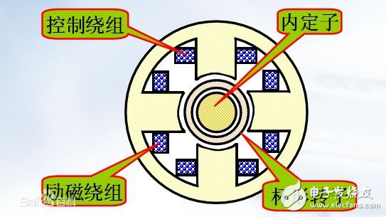
Field windingA field winding (also called an excitation winding) is a coil winding that can generate a magnetic field. Generally, in the motor and generator, there are series and parallel excitation. The excitation winding inside the generator can replace the permanent magnet, which can generate a strong magnetic flux density that the permanent magnet cannot produce, and can be easily adjusted, thereby achieving high-power generation.
A winding in a booster transformer that supplies electrical energy to a series winding. Excitation windings and armature windings are only available for synchronous and synchronous motors. A typical AC asynchronous motor has no field windings.
Introduction to field winding
The field winding has a single wave winding and a complex wave winding. The characteristic of single-wave winding is that all the coils under the same polarity are connected in series according to a certain rule to form a parallel branch. So the entire armature winding has only two parallel branches. In the commutator pitch of the wave winding coil, P is the logarithm of the magnetic pole; k is the number of commutator segments; a is a positive integer such that Ys is equal to an integer, which is equal to the logarithm of the parallel branch of the wave winding. The single-wave winding has a=1, and the a=2 complex-wave winding is called a double-wave winding. It can be regarded as a complex winding composed of two single-wave windings in parallel, so there are 4 parallel branches; a》 2 can be analogized, but used very little. Wave windings from the principle of parallel circuit connection, only two sets of brushes, that is, a set of positive brushes and a set of negative brushes.
The field winding design includes determining the number of field winding turns, wire gauge and excitation system requirements for rated field current and voltage. In the series motor design, the number of wire specifications should be minimized, so that the motor excitation current and the current specification of the excitation device are reduced, which is convenient for mass production.
According to the requirements of the excitation system for the rated excitation current, for example, the requirements of the rated current of the rotating diode in the brushless generator, the requirements of the rated voltage of the automatic voltage regulator, etc. The number of turns per pole of the field winding Wf and its wire gauge are selected from the rated excitation current IfN and the size of the magnetic pole.
Small and medium-sized generator excitation windings generally use enameled round wire or lacquered flat wire. The cross-sectional area of ​​the wire is determined by the selected current density jf. The jf is selected to be related to the insulation level of the field winding, the rotor structure (such as hidden pole type, integral salient pole type or split salient pole type) and ventilation effect. For generators with different specifications of the same frame, the longer the core, the smaller the value of jf should be. The range of values ​​of jf is 3.8 to 5.5 A/mm for Class B insulated generators, 4.5 to 7 A/mm for Class F generators, and 5 to 8.5 A/mm for Class H generators.
According to the process and structural requirements, the use of lacquered flat wire, 1.4 "b / a "8 (as shown), and the use of "winding" process to improve the resistance of the coil to the centrifugal force, on the overall salient pole structure, The number of coil layers is even, so that the head and tail lead wires of the coil appear at the bottom. If an enamelled round wire is used, the number of turns in the even layer should be one less than the number of turns in the odd layer.
The difference between field winding and armature windingThe field winding is a winding that generates an exciting magnetic field, and the armature winding is a winding that generates an alternating current output. For a synchronous generator of a direct current excitation, the exciting winding is the rotor winding of the generator, and the armature winding is the stator winding of the generator.
Excitation windings and armature windings are only available for synchronous and synchronous motors. A typical AC asynchronous motor has no field windings. The asynchronous motor is divided into two types: squirrel cage and winding type. The stator winding structure is the same. The squirrel cage rotor is a squirrel cage, and the wound rotor is a coil (the external rotor can change the rotor impedance to achieve shifting).
The so-called "armature winding" is the "main power loop" of the motor. Which of the rotor and stator coils is larger is the "armature". Needless to say, most of the stator coils are "armature windings".
Water Proof Axial Fan ,Compact Axial Fan,Axial Air Fan,Co Axial Fan
Hangzhou Jinjiu Electric Appliance Co Ltd. , https://www.jinjiufanmotor.com