The quality of the plant depends largely on the condition of the process instrumentation. In addition to sensors and transmitters for parameters such as flow, level, pressure and temperature, these instruments also include analyzers and control valves. What work do we need to do to keep the field instruments healthy and functioning without spending other resources? Here, the field experts will give the following measures that can be taken, and discuss the advantages and disadvantages of EDDL and FDTDTM for describing valve parameters.
Prescription #1: Correct selection
The first step in the maintenance of process instrumentation is to first make the correct selection. “Correct†here means “applicable to the actual applicationâ€. For example, you don't have to choose a sophisticated smart meter for low-priority work. However, for critical process applications, smart meters with FOUNDATION fieldbus, Profibus or HART communication should be used. TomWallace, global marketing manager at PlantWebEmersonProcessManagement, said that in places where control accuracy is critical, choosing the right instrument type is extremely important, for the simple reason that in the traditional 4-20 mA signal system, the transmitter section must include numbers. Analog converters, and the control system part must also include analog-to-digital converters, both of which produce bias and drift. He added that digital transmitters can provide and transmit large amounts of information in addition to this.
Second, use isolated transmitters; although most dcs and plc inputs are isolated, some devices and other noise sources often introduce large amounts of electrical noise into the system and cause errors. Using an isolated transmitter will help minimize interference from such noise.
In addition, we recommend that you do not rely too much on pressure, temperature and level switches to control the relevant parameters separately, as their faults are difficult to detect in time. A more reasonable configuration should be to use the switching signal as a backup for the continuous analog signal, because the continuous output of the analog signal can be easily monitored.
Prescription #2: Correct installation of the device
Even the best instruments in the world, if not properly installed, will not perform as they should, and may even be permanently damaged. Therefore, be sure to pay attention to the following points during installation:
· The location of the device. For example, a pressure transmitter cannot be installed on top of a steam line or a continuous drain condenser because in this case the sensor is exposed to the circulating steam environment for 100% of the time.
· Pipeline arrangements. Make sure that the upstream of the flowmeter has a straight section that is long enough or that has a flow regulator installed.
·installation. Install the meter in the proper direction: the gas is facing up and the liquid is facing down.
·wiring. Carefully arrange the wiring of the pulse tube. If it is practical, try to cancel it.
·power input. Ensure the reliability of the instrument's power supply, no electrical noise, power surges and spikes.
· Grounding. Some instruments, such as direct reading frequency meters, must be properly grounded. Make sure the shielding system is grounded only at one point.
· Ambient temperature. If the sensor or transmitter is operating outside of the rated temperature range, its life will be greatly reduced.
· Corrosive gases. According to Scott Saunders, vice president of marketing and sales at Moore Industries-International, the chemical industry often sees the following: "When workers connect RTD (resistance thermometer) measurements to the transmitter, they often operate as follows. Maintenance personnel put RTD Installed in a new application, and it seems that all operations are normal. After six months, the maintenance personnel inspect the instrument in accordance with the preventive maintenance program, first remove the wires of the RTD, and then connect the RTD signal simulator. Put it in a certain temperature file, and then coordinate with the control room to ensure that the signal check goes to the full range, and the readings are consistent at the check points of 4, 12, 20 mA. Once the inspection is completed, the wiring of the RTD and the transmitter is restored. However, the largest measurement error is now introduced again throughout the measurement system, ie the wires of the three-wire RTD are corroded." When we use a three-wire RTD, the premise is that the impedance of the wire does not change. However, when the RTD is in a corrosive atmosphere, the wire impedance increases with time. In this case, the choice of a four-wire installation will minimize the error caused by this problem.
· Installation of the ClassIDiv.1 area. Saunders said: "I was very surprised to find that a large number of instrument enclosures belonging to ClassIDiv.1 - explosion-proof enclosures, did not seal well under the connecting threads. I even found that this class of meters is starting to be used. During the calibration and wiring, although the glass cover is also provided, the connection thread is not screwed to the end, and the gasket is pressed from the beginning to the end. These threads exist there for only one reason: before the gas hits the air. Just cool it first.".
Once the meter is installed, the first priority is to verify the rationality of the setup and installation. We can use the device's self-diagnostic tool to check for installation errors. If the meter has emulation mode, you can also use this feature to check and make sure everything is working properly, Emerson's Wallace adds.
Prescription #3: Let it be natural
Once the meter is in place and functioning properly, the best way is to let it go, until it issues a fault alarm. “High-grade instruments are very reliable and accurate. After installing them in the factory, there is basically no need to verify them. You can directly apply the calibration data of the instrument manufacturer, and then only need to install the instrument in the correct orientation and process media. After the pulse tube is full, perform a zero calibration. You will correct it zero next time, maybe it is already ten years later. Wallace also pointed out that unless the range needs to be changed again, the instrument is repeated. The test is often counterproductive. You should learn how to consult the documentation provided by the instrument manufacturer. He added: "The calibration performed by the instrument manufacturer is often better than the calibration performed by the user at his own factory or site. â€
As shown in the schematic provided by Emerson Process Management, ensure that the upstream of the flowmeter is either long enough straight pipe length (a) or fitted with a flow regulator (b).
According to Emerson Process Management, the wiring of the pulse tube must be carefully and, if possible, minimized.
MooreIndustries' Saunders said that the above practical applications are effective for two reasons: "First of all, these devices are very reliable and their prices are not too expensive, so once a major failure is discovered, we can do it right away. Replace with a new one.†Second, digital meters have built-in self-diagnostic tools that can be alerted in a timely manner based on online status monitoring if hardware or software fails.
Some maintenance personnel, after reluctance, gave up the habit of repeating the regular calibration of the instrument. To make it believe that duplicate calibration is really unnecessary, the best way is to build a database. A calibration instrument capable of data archiving will help, but sometimes it is such a database that often misleads everyone. Saunders said, "Some people are often willing to invest in new technologies, such as FOUNDATION fieldbus or Profibus, but do not have a corresponding middle layer, such as asset management optimization packages to take advantage of digital data such as status bits, parity and drift. â€
MooreIndustries-International recommends that for instruments used in Class I, Div.1 explosion-proof areas, such as a field-mounted transmitter for measuring the surface temperature of natural gas pipelines, the housing screws must be tightened down and the pads pressed Film, thus ensuring the corresponding explosion-proof grade.
Such a “set, then forgotten†concept does not apply to the measurement of safety and critical applications where process equipment is to be verified; likewise, for equipment that is used in demanding applications or that may be contaminated or worn, Not applicable. Analytical equipment and valves also fall into this category. Special maintenance is also required if installed in corrosive, abrasive, severely vibrating or extremely hot environments. In addition, the above concepts are not applicable to the maintenance of certain valves with moving parts that vary in characteristics over time and application.
Prescription #4: Observing listening to various signs
One way to determine if a meter is functioning properly is to check the noise of the process. If the reading of a meter does not change within a few weeks, there are two possibilities: one may be that the process is very stable, and the other may be that the meter is damaged. Emerson's Wallace said, "I remembered when installing the analyzer once, a technician said, 'This PH meter has been set at 7.2 for 18 months', and later found out that the reason is the past 18 months. The probe of the analyzer has been completely covered by dirt. As a result, the probe has no way to measure the current actual parameters. Sometimes, there is a certain process noise in the signal, which means that the instrument is in normal working condition and there is no 'dead. Drop '.'
Some transmitters have a built-in function module with a damping factor of a few seconds, which reduces the process noise, and it is the noise signal that reflects whether the meter is in normal operation. However, if we are using a FOUNDATION fieldbus or Profibus meter, then even if the noise is not significant in the signal of the process variable, the meter can display it as a digital signal. This feature is very useful for tracking the standard deviation of process noise. “The increase in noise means several possibilities: entrainment of air in the process steam, surge flow, or insertion of pulse lines, etc.†Wallace said. “If this happens in the oil and gas sector, then it is possible to reflect the fluid. Contains sand.
Prescription #5: Focus on secondary variables
Many modern meters collect more than one variable data, although usually not all. For example, many pressure and flow meters also measure temperature—process temperature, or the temperature of the meter itself—and maintain a relevant record inside the meter for later reference. Paul Schmeling, pressure product marketing manager at Emerson Process Management, said, "Electronic devices have their best operating ambient temperature. For example, a platinum resistance thermometer (PRT) built into the circuit can determine if the temperature of the associated electronics has exceeded its rating. range.
Prescription #6: Seriously handle the necessary alarms
A meter can record the range of pressure changes it has experienced through a reasonable setting. Some abnormal conditions may shorten the life of the meter, and may also cause the zero drift of the meter. We can set up such a signal to the meter to inform the user of the following information: the meter should now be checked; the heat transfer that should have been turned off is still open, or vice versa.
If we intend to monitor all possible data in the system's digital meters, the biggest problem is the so-called "alarm flood." When the process is disturbed, there will be an endless stream of warning signals from many places, and the poor operators may be completely submerged in the "alarm flood", but the alarms that may cause potentially terrible consequences cannot be made in time. Effective response. Perhaps the most familiar one is the nuclear power plant accident in San Francisco on the United States in 1979, which caused almost a nuclear disaster. In addition, there have been similar accidents in the United States and other countries.
The most effective way to prevent this is to include all alarms in the alarm management system (for example, an industry standard requires only six alarms per hour). The current DCS system has some intelligent software tools that can assist with this. Item function. If there is no emergency, it is best to ignore some minor alarms that are unlikely to cause major problems.
Charlie Piper, Fieldbus Product Manager at InvensysFoxboro, said: "Many devices have both warning and alarm limits, and indicate the urgency of the problem through high-level alarms, high-limit alarms, etc. Some devices may have up to 20 -30 warning limits or alarm limits, so the system can take into account the differences between these limits and, depending on the situation, trigger different sequences of actions."
Prescription #7: Turn data into information
All data obtained from smart sensors or transmitters does not make much difference if no correlation analysis is performed. MooreIndustries' Saunders said, "Many users have installed almost all the tools to get data, but they lack the data processing and reporting process, and there is no software that can provide predictive maintenance. This is the return on investment. Or necessary to properly calibrate the meter. The asset management system can save considerable maintenance costs because it can generate some useful information and promote the maintenance of equipment from preventive maintenance to predictive maintenance.
The asset management system is also very helpful for valve positioners, says Pipeboro's Piper. "You can track the number of times the positioner is reversed. Usually, it can also be used to track the cumulative stroke of the valve stem." And you can also tell At some point when some components are getting worse, he explains, “In most valve positioners, there are a lot of equipment parameters. For example, it can reflect the 'excessive deviation' of the valve stem's resistance, and the control command. It may be that the valve is opened to an opening, but the actual position cannot be reached." However, by observing the 20 or 30 related parameters provided by these devices, it is possible to trigger the sequence of actions as needed to solve the above problem. ,He said.
“If you can apply the asset management system and the right software well,†adds Saunders. “Then you can frequently test the various characteristics of the valve characteristics, observe whether the component drifts, or give predictive maintenance ( PM) schedule.†He mentioned that there was a user who calculated the frequency of a valve reaching the seat and found that the frequency was not very high. There is no need to arrange a predictive maintenance plan. What is interesting here is that the user made the above judgment not based on the asset management system, but only through a simple HART interface module, which triggers a signal input to the DCS system whenever the stem position is less than 1%. .
Based on the data collected by the asset management system and correlated analysis, it is possible to give a set of predictive maintenance strategies. However, in some cases, it may be a better choice to adopt old-fashioned preventive maintenance and even failure and maintenance strategies. For example, for a large tank that takes a week to fill or empty, it is not very urgent if its level transmitter fails.
"The most sensible approach is often to do nothing."
In short, if the latest technology is used, or if the device is not a critical component, then the most sensible thing is to do nothing. Wallace said, “If a part of the instrument or terminal component is prone to wear or contamination, and its measurement parameters involve safety, environmental, or significant economic impact, then preventive maintenance or predictive maintenance is necessary. Next, you need to shift the concept of preventive maintenance or predictive maintenance from 'going out to work' to 'real-time monitoring, and automating diagnosis if needed'. In fact, one of the biggest reasons for instrument failure is : Indiscriminately, do not do rigorous analysis, go up and operate or repair the meter. Therefore, if the consequences of the instrument failure may not be serious, the best thing to do is to leave it alone until it is completely broken and replace it.
Describe valve parameters: EDDL or FDTDTM
Regarding the best communication method between the field device and the control system, each manufacturer can be described as a matter of opinion and fierce debate. Currently, in the "Fieldbus War", there are supporters of FOUNDATION fieldbus, Profibus, and other protocols that are trying to compete for dominance. There is also no consensus on how to optimally handle the settable parameters in the field device and the way it is presented to the user. On the one hand, some vendors support Device Description Language (DDL), and have now evolved into Electronic Device Description Language (EDDL); on the other hand, some vendors prefer Field Device Tool Device Type Management (FDTDTM) technology. .
The earliest, older technology was the device description (DD) file that the manufacturer developed in the year, including the basic data for each device. After the host obtains the data, it is then presented to the user. Martin Zielinski, head of HART and fieldbus technology at Emerson Process Management, said, "When field device manufacturers describe the correlation of parameters and how they should be grouped, how to display them, the exact format ultimately depends on the host." FDTDTM technology is for field devices. Standard environment designed for maintenance and configuration. DTM is a technology for device maintenance and diagnostics that can be used as a plug-in for the engineering and asset management system software of a host system. Unlike the device description language, the DTM plug-in provided by the device manufacturer includes a user interface for device management and maintenance. This technology enables device manufacturers to develop their own host applications and control how users navigate the interface and what interfaces display. information.
The latest technological advances have made the distinction between the two technologies in some respects less obvious. EDDL has enhanced its graphics capabilities, "Users can draw charts and graphs. By using a unified data storage method, relevant information can be stored on the system hard drive and retrieved in the future when needed," Zielinski said.
Foxboro's Piper said: "The above enhancements have already begun to build configuration screens. Unlike the original simple parameter tables, users can now put various parameters on different screens, group them reasonably, and give them which parameters. To make a selection with the drop-down menu, the user display has been improved from the blank form to become more like a tabular form."
But no matter how the device description (DD) technology is enhanced, there are some limitations from the host manufacturer's point of view, Piper said. "Because each valve is different, we can't develop a user interface for each valve. Then, this work has to be undertaken by the valve manufacturer." He still advocates that FDT is the best technology to solve this problem. â€
On the other hand, Emerson's Wallace believes that "EDDL technology has great potential to get the most benefit at the least cost." He also cited the level of user support as evidence of his views. "There are about 1,200 kinds of current. Field devices use EDDL, and only about 110 devices use DTM.†He added, “EDDL is a global standard that is supported by almost all host manufacturers.â€
In this regard, Piper expressed a different view, "In addition to individual manufacturers, almost every system manufacturer has announced support for FDT technology."
Wallace recommends that you give some support to both technologies. He said, "My suggestion is to use EDDL technology as much as possible and use it as a standard technology. Only when EDDL, application packages, and snap-inssnap-ons using EDDL. When all the technologies are not suitable for the required functions, consider trying DTM."
Applying DTM technology will make the following functions possible: Device manufacturers can include features such as Microsoft Windows Help on their display screens. As shown in this screen provided by InvensysFoxboro.
Power Bank (Mobile Power Pack, MPP), also known as charge treasure, travel charger. A set of power supply and charging functions in one portable charger, you can give mobile phones, tablet computers and other digital equipment charge anytime, anywhere. Generally it consists of a polymer or lithium batteries (Rechargeable 18650 Lithium Battery Power Bank and Lithium Polymer Battery Power Bank)as an electricity storage unit, easy to use and quick.
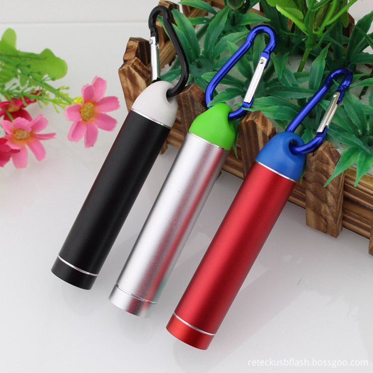
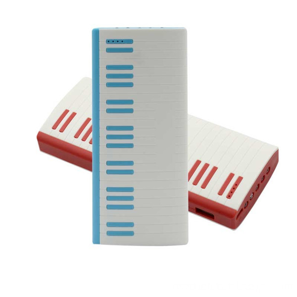
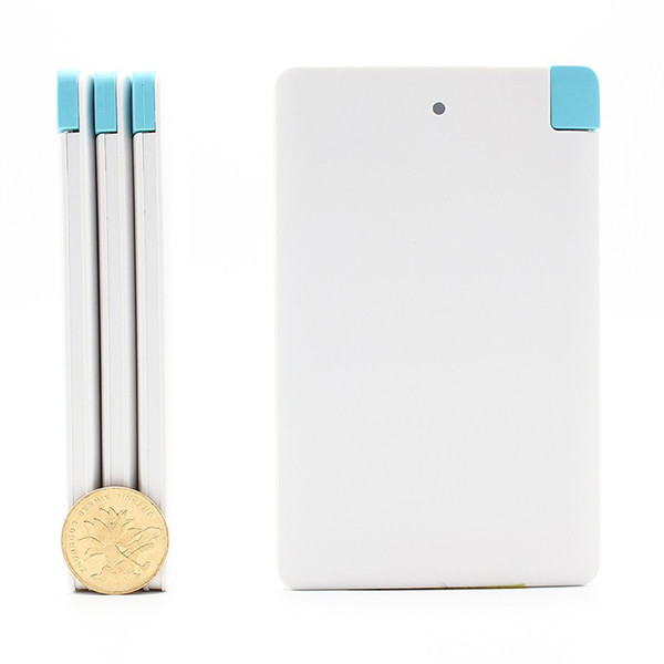
Power Bank Includes a lot of types, Such as AC plug type Power Bank, LCD screen Power Bank, Stylish Mini Portable Power Bank, Built-in rechargeable line Power Bank, Led lighting Power Bank, solar Power Bank, Tablet Power Bank, Wireless Power Bank.rohs power bank,power bank charger battery,bank power battery pack,warranty power bank,power portable power bank

Mobile power usually designed lightweight, compact, easy to carry, to facilitate mobile use. After fully charged mobile power charger, you can charge digital products four or five times electric, with the appropriate connectors connect your digital devices or directly connected USB On-the-Go (USB-OTG) portable with usb cable type equipment, mobile power through automatic detection or simple switch to start your digital devices powered or charged.
Usage:
1. Power Bank for Phone charge:
2. Power Bank for Tablet:
3. Power Bank for The digital camera and a video camera:
4. Power Bank for Other compatible devices
In fact, if the charging voltage is 5V and the current of all devices within the mobile power can withstand a range of mobile power can be used, as long as the relevant charging port, can be used mobile power charging.
Power Bank,Lithium Battery Charge Power Bank,Lithium Polymer Battery Power Bank,4000Mah Lithium Charge Battery Power Bank
Reteck Electronic Co., Ltd. , https://www.reteck.com