The car's power transmission mechanism is essentially an engine that powers the car (traditional internal combustion engine) and transmits the power to the gearbox, the drive shaft and the system that ultimately reaches the car's wheels. The electrification of the transmission system is gradually changing the future development of automotive technology, as well as from sustainable energy drivers, improving fuel efficiency and complying with relevant CO2 emission regulations.
In addition, the current key technology drivers are focused on improving handling and durability, as well as new practical technologies such as inverter technology that is generated in response to regenerative braking, which can be used to power electric motors or to charge batteries.
During the development of any part of the power transmission, various electrical and physical parameters related to mechanical performance need to be measured in order to achieve a complete test process. The electrical signal comes from the power circuit that links the high voltage battery and the inverter, while the physical parameters occur during the electrical to mechanical conversion process. In order to thoroughly understand the performance of the entire system, it is necessary to measure the electromagnetic power converter and the power circuit, and analyze the powertrain management system data from the operation on the automotive serial bus network such as CAN. In addition, these tests must be performed simultaneously to achieve an overall optimized solution, rather than just optimizing a component individually.
The traditional approach is to measure electrical and physical parameters in a car using a data logger or data acquisition system with a sampling rate of up to 10,000 samples/second. Such systems typically provide a number of channels that allow the user to combine multiple sensor outputs with isolated input channels to measure electrical systems (often including floating voltage values) as well as physical parameters such as temperature, vibration, and pressure on materials.
Car version ScopeCorder
The trend toward electrical mobility has led to the increasing use of power inverters, and with these components supporting higher frequencies and higher voltages, there have been isolated measurements at speeds of up to 100 million samples per second (100 MS/s). Claim. These sample rates were previously achieved with an oscilloscope combined with a differential probe that allows engineers to observe transient voltages and currents at higher frequencies. A more interesting area is the powertrain management system, which operates on a car serial bus such as a CAN network and continuously delivers engine performance parameters such as engine temperature, speed and pressure values. Obtaining electrical signals, physical performance parameters, and data in the drive management system in a single measurement operation poses considerable challenges.
To reduce the time and effort required to integrate these numerous parameter records, Yokogawa developed the DL850V ScopeCorder Vehicle EdiTIon instrument, combining the advantages of high-speed display and traditional data capture recorders in a single portable package. The ScopeCorder can capture and analyze transient events that can last only a few milliseconds, as well as full powertrain durability testing for up to 30 days.
The latest automotive version of the DL850V ScopeCorder instrument features channel isolation, signal conditioning and high channel count. It also incorporates CAN and LIN bus monitoring to assist users in decoding CAN or LIN signals and monitoring transmitted physical data such as engine temperature. Wheel speed, acceleration and pressure. These values ​​are then compared to the data from the actual analog sensor. By combining multiple high voltage and current signals (sampled up to 100 MS/s) with physical parameter measurements (such as temperature, pressure or vibration, and decoded CAN bus signals), the DL850V creates a single complete measurement file, as shown in Figure 1. . Compared to other methods in which the measurement files of multiple measuring instruments must be integrated for analysis on a PC, this method can significantly reduce the time and effort required to analyze the entire system.
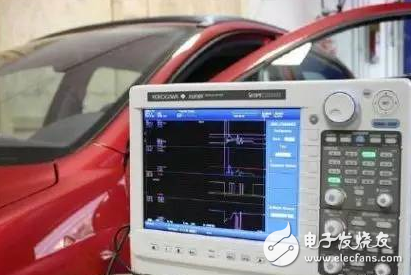
Figure 1: A single measurement file created on the DL850V that combines multiple high voltage and current signals, physical parameter measurements, and decoded CAN bus signals.
Power electronics in automotive applications
Inverters in automotive applications are increasingly using faster, higher voltage components, which requires isolated high-withstand voltage measurements with higher sample rates and the ability to simultaneously simultaneously for longer periods of time Measure a larger number of signals. Traditional waveform measuring instruments like digital storage oscilloscopes have very limited capabilities for high voltage inverter measurements because they lack separate isolated inputs, high voltage isolation and 12 or 16 bit resolution. Other waveform measurement solutions typically require an external (active) signal conditioning circuit to achieve high voltage isolation.
On the other hand, the DL850 ScopeCorder uses a technology called isoPRO in its high-voltage measurement module that provides 100MS/s sample rate, 1kV isolation and 12-bit resolution without the need for external active signal conditioning equipment.
The isoPRO technology uses a system that converts digital data into optical signals using semiconductor laser diodes, and the converted optical data is transmitted to the instrument through the optical fiber. Since semiconductor laser diodes have a particularly high data transfer rate, a large amount of data can be transferred through a single device, so the isolation region can be made very small.
In addition, since the fiber itself is insulated, the signal transmission distance along the fiber is sufficient to provide proper insulation, so that the insulation distance between the signal input and the main unit can be ensured even at a high voltage of 1 kV. With the isoPRO technology, two channels with a 100MS/s, 1kV high withstand voltage isolation measurement circuit can be packaged in a compact module measuring approximately 100 & TImes; 200 mm.
Another benefit of this technology is the ability to provide superior noise rejection. Since the switching speed of the high voltage inverter is fast, noise can be introduced into the measurement path. However, in high-voltage isolation modules, high-quality noise suppression performance can bring good common mode rejection ratio (CMMR), and for inverters and devices such as IGBTs, common floating voltage switches can usually be captured with high precision. Waveform, see Figure 2.
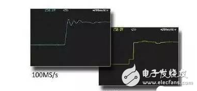
Figure 2: Inverter signal pulse waveform measured using the DL850 ScopeCorder module. On the left is the measurement with a sampling rate of 100 MS/s and on the right is the result measured with the earlier 10 MS/s unit.
Mechanical/entity parameter value
The engine test bench is a facility for developing, characterizing, testing, and simulating powertrain systems. A complex engine test bench contains a variety of sensors (or converters), data capture functions and actuators that can be used to control engine status. The DL850 DscopeCorder has a modular structure and numerous input modules to monitor mechanical and electrical signals. The converter converts the signal from the engine into a form that the input module can understand - typically a voltage signal. For example, a tachometer is used to measure the engine speed in revolutions per minute. This will generate a voltage output or a pulse output signal, then send this signal to the ScopeCorder for pulse output processing and display the actual acceleration pattern after the display - even extending the mechanical/electrical phase difference, see Figure 3.
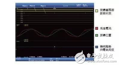
Figure 3: Rotary encoder signal used to calculate the trend of the angle of rotation.
Thermocouples (usually K-type components) can be utilized by using temperature modules. These thermocouples are inexpensive and have sufficient precision to accomplish the task. Each input module has up to 16 thermocouples connected to the instrument. To monitor the vibration of the powertrain components, an acceleration module with a piezoelectric sensor can be used.

Figure 4: DL850V Vehicle EdiTIon decodes CAN and LIN bus information and displays both analog and electrical or mechanical signals on the screen
Automotive serial bus
The CAN or LIN network inside the car is connected to an electronic control unit (ECU) that transmits many parameters and control signals such as temperature, wheel speed, acceleration and pressure through the network. The automotive serial bus and ECU unit together form the powertrain management system. This means that not only the electrical and mechanical signals from the analog sensors can be measured during development, but also the physical parameters transmitted on the serial bus of the car can be measured as a reference for the electrical and analog sensor output parameters. The DL850V Vehicle EdiTIon decodes these CAN and LIN bus information and displays both analog and electrical or mechanical signals on the screen.
Figure 4 shows an example of this. This feature can be used to directly map the relationship between data transmitted on the car's serial bus and electrical and mechanical values, allowing real-time observation of system behavior. The DL850V supports CAN-dbc files (developed by Vector Group) and LIN network definition files, allowing users to easily select CAN and LIN information of interest.
Summary of this article
The DL850V ScopeCorder provides all the measurement and analysis tools of modern digital oscilloscopes, including cursors, waveform parameter calculations, math and DSP channels, and fast Fourier transforms. It also acts as a multi-channel data capture unit/recorder that integrates electrical, mechanical and automotive serial bus measurement functions in a single device. In most cases, users can analyze data and get results immediately, without the need for offline post-processing steps.
All in one pc is a new trend for desktop type computer nowadays. What you can see at this store is Custom All In One PC. There are 19 inch all in one pc, 21.5 All In One PC, All In One PC 23.8 Inch and 27 inch all in one pc, which are the main sizes at the market. How to choose the most suitable one for special application? According to clients` feedback, 19.1 inch entry level, 21.5 inch middle and low level, 23.8 or 27 inch higher level-All In One PC I7. Some clients may worry the heat-releasing since equipped releasing fan into the back of monitor, see no releasing fences on back cover. However, totally no need worry that point, cause special back cover material and releasing holes can meet the demand of heat releasing.
You can see All In One Business Computer, All In One Gaming PC, and All In One Desktop Touch Screen series at this shop.
Any other unique design or parameters, just feel free to contact us so that can get right and value information quickly.
Believe will try our best to support you!
All In One PC,All In One Pc I7,Custom All In One Pc,All In One Pc 23.8 Inch,21.5 All In One Pc
Henan Shuyi Electronics Co., Ltd. , https://www.shuyicustomlaptop.com