A 6-inch flexible PEDOT touch panel fabricated on a PI (polyimide) film requires an etch-free process and a "multi-purpose flexible electronic substrate technology." In the flexibility test, the resistance change (ΔR/R0) of the PEDOT electrode decreased by 1% after the 10K winding test. With the help of video switching system, picture exchange system and zoom in/out function, the technical integration of 6-inch PEDOT touch panel and AMOLED display module has been successfully demonstrated.
1 IntroductionTransparent doped metal oxides such as ITO (Indium Tin Oxide) have been the main choice for applications such as liquid crystal displays, touch panels, OLEDs (organic light-emitting diodes), and solar cells. However, the metal oxide film is extremely poor in flexibility and usually produces cracks 1 during bending or twisting. Therefore, a variety of flexible electrode materials have been considered as an alternative to ITO, such as PEDOT: PSS polymer 2, carbon nanotubes 3, graphene 4, and nanosilver wires 5. Compared with other alternative materials, the liquid conductive polymer PEDOT, which is currently widely concerned with 6-8, has a variety of core competitive advantages, including lower haze, more affordable, and can be combined with gravure and squeezing extrusion. The coating is compatible with solution deposition techniques such as slit coating. This article will examine in detail the use of highly conductive PEDOT as a transparent electrode in flexible touch panel applications, including optical performance, reliability, and flexibility testing. In addition, the results of the integration of PEDOT touch panels and AMOLED display module technology will also be verified.
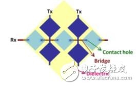
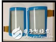
2. Method 2.1 Production processThe highly conductive PEDOT product formulation (produced by Taiwan EOC Co., Ltd.) mentioned herein is used as a transparent conductor. Figure 1 (a) and (b) show top and cross-sectional views of the PEDOT touch panel structure. FlexUPTM substrates are produced by applying a polyimide varnish over a single release layer. Subsequently, a transition layer is deposited on the substrate by a vacuum deposition process. Silver plays a role as a bridge through the mapping process. Thereafter, the isolation layer generates a dielectric layer by a deposition and pressing process. After the conductive polymer is introduced through the spin coating process, the visual drawing process 9 is used for pressing, and the final step of the touch sensor manufacturing process is completed. At this point, the touch sensor can be detached by mechanical debonding technology.
(a)

(b)
(a) top view of the flexible PEDOT touch panel; (b) side cut view of the flexible PEDOT touch panel
2.2 Flexible testThe flexibility of the PEDOT electrode applied to the FlexUpTM PI film needs to be evaluated by a bending test. The bending radius, cycle time and bending curvature referred to herein are 5 mm, 10000 and 2 sec/time, respectively.
2.3 Integration with AMOLED display moduleAs shown in Figure 2, the 6-inch PEDOT touch panel is overlaid on a 6-inch AMOLED display module by means of an optical adhesive (OCA) film. After the lamination process is completed, the integrated module is detached from the carrier glass by a debonding process.
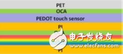
Figure 2. Detailed illustration of the technical integration of the PEDOT touch panel with the AMOLED display module
3. Results and discussionThe film resistance and thickness variation of the PEDOT film product produced by the spin coating process can be achieved by adjusting the spin coating process. Figure 3 shows the optical performance characteristics of a PEDOT film. The PEDOT film has an ideal haze value ("1%") and is very stable. The red, green and blue light transmittance will increase as the resistivity of the film decreases. When the film resistivity exceeds 70 Ω/□, the transmittance will be higher than 80%. For touch panel applications, it is recommended to control the film resistivity and transmittance of the PEDOT film product in the blue dashed area (as shown in Figure 3).
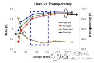
Figure 3: Schematic diagram of the relationship between PEDOT film resistance and optical properties
In order to confirm the minimum line width of the PEDOT electrode, a specially designed test key with different line widths was used in this test. Line widths are 75um, 150um, 200um, 250um, 300um and 350um. After the passivation treatment using the PEDOT etchant, when the line width is greater than 200 μm, the line resistivity of the PEDOT electrode is slightly increased as the etching time increases, and the line width is a very small width of less than 200 μm (as shown in FIG. 4). Show) there has been a significant increase. In order to ensure that the line resistivity of the electrode is lower than 15KΩ, a circuit with a line width greater than 200μm is recommended for the specifications required for the touch panel integrated circuit.

Figure 4: Schematic diagram of the relationship between PEDOT film resistance and line width
In order to detect the flexibility of the PEDOT electrode, a PEDOT electrode test button needs to be mounted on the bending machine. The bending radius of this machine can be adjusted from 5 mm to 50 mm by adjusting the bending angle, while the bending cycle can be calculated by the embedded automatic recorder. Figure 5 is a screen shot in the bending test. For example, when the bending angle is 0 degrees, the bending radius is 5 mm. In this flexibility test, the line resistance of the PEDOT electrode will be checked after an inward/external bending test with a bending radius of 5 mm for 10,000 weeks.

Figure 5: Bending test equipment
Figure 6 shows the results of the inward/outward bend test of the PEDOT electrode. The bend radius is 5 mm and the number of bends is 10,000 cycles. The structure of the PEDOT test electrode is simulated based on the actual touch panel structure - PET is overlaid on the PEDOT electrode/PI film with optical glue. After a 10000-week inward/outward bend test, the resistance change rate of each PEDOT electrode was less than 1%.
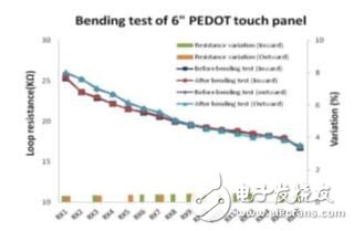
Figure 6: Detailed diagram of electrode resistance change on PEDOT 3 test key mode after 10,000-week bending test
The FT6306 touch panel IC with this design pattern and produced by FocalTech is used to detect the function of the PEDOT touch sensor. Fig. 7(a) shows a PEDOT touch panel which is subjected to a lamination process by a decorative PET film. This decorative film is used to improve the mechanical properties of the PEDOT touch panel - this touch panel is produced on a PI film with a thickness of 15 μm. Figure 7(b) shows the drive test results for a 6-inch PEDOT curved touch panel. A 6-inch PEDOT touch panel mounted with an FPC (Flexible Printed Wiring Board) is bonded to an arcuate carrier. The performance of the 6-inch PEDOT curved touch panel has been successfully demonstrated with features such as hand-drawn, picture exchange, zoom in/out and rotation.
(a)

(b)
Figure 7: (a) 6-inch PEDOT touch sensor photo; (b) 6-inch PEDOT touch panel function test
Figure 8 shows the drive test results after the technical integration of the 6-inch flexible AMOLED display module and the PEDOT touch panel. The above device is fixed on a curved wearable carrier by a bonding process. With the help of video switching system, picture exchange system and zoom in/out function, this 6-inch PEDOT touch panel integrated with AMOLED display module has been successfully demonstrated.
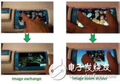
Figure 8: Functional test after technical integration of 6-inch flexible AMOLED display module and PEDOT touch panel
4 ConclusionThe production of the 6-inch flexible PEDOT touch panel combines the PEDOT graphics process with the Multipurpose Flexible Electronic Substrate Technology (FlexUpTM). After technical integration with AMOLED display modules, the performance of this product has been successfully demonstrated through hand-drawn, 5-point touch and zoom in/out functions. After a 10,000-week inward/external bending test with a radius of 5 mm, the resistance change rate of each PEDOT electrode was less than 1%. According to the above test results, transparent, highly conductive polymer PEDOT is expected to be applied to the field of flexible touch panels.
Power Cable,Power Cord,Vfd Cable,Armor Power Cable
Baosheng Science&Technology Innovation Co.,Ltd , https://www.cablebaosheng.com