The TL431 is a three-terminal programmable shunt regulator diode whose voltage reference operates like a low temperature zener tube and can be programmed from 2.5V to 36V with two external resistors. At the same time, the device exhibits a wide operating current range of 1.0mA to 100mA at a typical impedance of 0.22Ω. The characteristics of these references allow them to replace Zener diodes in many applications that require precision voltage references, such as digital voltmeters, power supplies, and op amp circuits. The device is now widely used in a variety of switching power supplies.
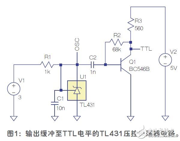
Under certain conditions such as supply voltage input and capacitive load, the TL431 will exhibit instability, causing continuous oscillation from 10kHz to 1.5MHz (the frequency depends on the control of the input voltage). Part of the reason is that there is a negative resistance zone under the above conditions. In this design example, the instability is neither caused by the internal poles nor by the third pole of the external capacitor in series with the load resistor. A single-transistor output stage is added to provide buffering to produce a TTL output level over the entire range (Figure 1).
Voltage controlled oscillator operation
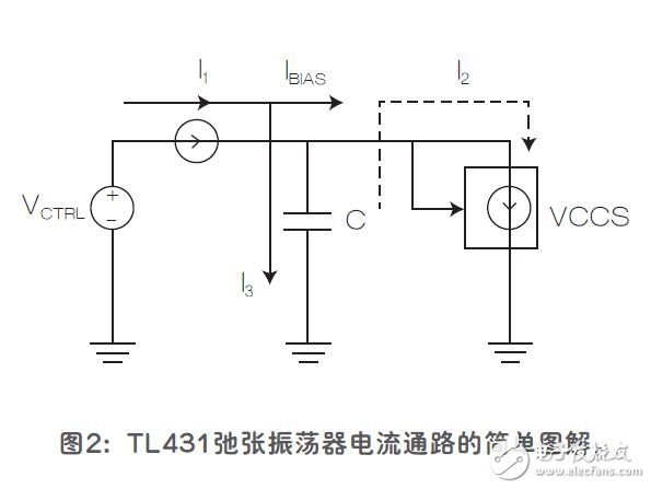
To understand the operating principle of the oscillator, you need to consider the circuit in two ways: The first is the underlying operation of the TL431 voltage reference. The oscillator equivalent circuit shown in Figure 2. Current I1 (see Figure 3) is a varistor constant current having a magnitude of approximately (VCTRL-VKA) / R (VKA is the Zener voltage). Assuming that the capacitor is not energized at the beginning (when VKA = 0V), then the capacitor is gradually charged by the current from I1 until the voltage reaches the equilibrium value of TL431, ie: VKA = 2.49V. As long as the charging current is present, the capacitor will continue to charge. The transient simulation of the circuit in Figure 2 shows that the capacitor voltage only needs to exceed the VKA equalization value by a few microvolts to initiate equalization recovery feedback, as follows:
Since the base of Q1 is directly connected to the capacitor, an increase in the VKA value causes the value of the emitter voltage of Q1 (that is, the base voltage of Q11) to become larger, forcing Q11 to perform more actions. Transistor Q9 and resistor R8 form the collector load of Q11. The increasing collector current in Q11 will reduce the collector voltage of Q9. Q9 and Q10 are both components of the current mirror, so their collector currents are the same as Q11, but the dynamic collector load of Q10 consists of Q6, which is composed of the second current mirror through R5 (consisting of transistors Q2, Q4 and Q12) ) The base current is obtained. Because of the configuration of the current mirror, the initial increase in the Q1 emitter voltage also causes the VBE to rise. This increases the collector current of Q6, which in turn increases the collector current of Q10. Therefore, the overall effect is the increase in the collector voltage, which is the base voltage of the first transistor in Darlingtonpair Q7 and Q8, forcing Q8 to do more, resulting in its collector - The emitter voltage (VCE, actually VKA) dips. In this particular application, the reference terminal (R) connected to the capacitor is hardwired to the cathode terminal (K). Thus, to date, when the capacitor voltage exceeds the equilibrium value, the device can cause the cathode-anode voltage to rapidly decrease to return to equilibrium.
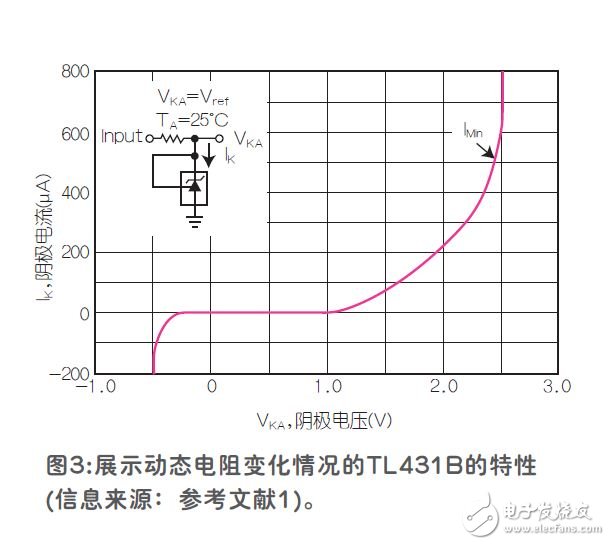
Figure 3 shows, in schematic form, how the continuous oscillation begins and is enhanced when the internal equalization value of the TL431 device is disturbed. The current in the capacitor is a small constant current derived from the supply current I1. In Figure 1, the charging current is I3. When the value of the capacitor exceeds the equalization value of VREF, the current I2 flows quickly and effectively absorbs the charging current stored in the capacitor. I2 is present for a short period of time, but it is sufficient to reduce the capacitor voltage to an equilibrium value again. Next, I1 will charge the capacitor again, maintaining steady state oscillation during this cycle. Since the discharge time of the capacitor is extremely short, it can be known from the following calculation formula that the current during discharge is much larger than the source current I1: I = ΔQ / Δt (where ΔQ is the charge current obtained by the capacitor in the charging phase).
All In One Business Computer is the one of the important All In One PC series, can meet all enter and normal business application scenarios. Therefore, more and more clients choose and recommend this Business All In One Computer for business or education projects. The Best All In One Computer For Business is the similar Apple design, competitive and attractive, the hottest parameters is 19 or 21.5 inch intel i3 or i5 2th or 3th or 4th 4 gb ram 128GB ssd . There are many other all In One Computers For Business with lighter weight. Of course, you can see Colorful All In One Gaming PC, All In One Desktop Touch Screen and All In One Business Pc. Believe you can always find the right one at this store. To save time, You can also contact us by email or calling directly to get matched and valuable information fast.
Any other special configuration interest, also feel free to let us know, will try our best to back you up.
Except all in one Custom All In One PC, 14 inch Education Laptop and 15.6 inch business laptop also available here.
All In One Business Computer,Business All In One Computer,Best All In One Computer For Business,all In One Computers For Business,All In One Business Pc
Henan Shuyi Electronics Co., Ltd. , https://www.sycustomelectronics.com