Combined with the application practice, the method of reducing the cost of the plc system is introduced from two aspects of hardware and software. Some design techniques are proposed, and specific analysis is made by means of different wiring diagrams and ladder diagrams. These techniques are applied in the process of applying PLC system. Has a very good practical value.
1 The need to reduce costs As a new type of general-purpose automatic control device, PLC has many functions such as strong function, high reliability, flexible and convenient use, easy programming and strong adaptability to industrial environment. Therefore, it has become more and more widely used in industrial automation, mechatronics and traditional industrial technology transformation, and has become one of the three pillars of modern industrial control.
With the continuous improvement of PLC products and the development of network technology, PLCs in the production field have begun to develop in the direction of networking. PLCs are used in various aspects of production. In this context, the price of PLC products and the cost of control systems become enterprises. The focus of attention will also fundamentally affect the application and promotion of PLC technology; based on this, this article provides some simple design techniques, which can reduce the cost to a certain extent and promote the widespread use of PLC.
In the process of actually using the PLC, the cost of I/O points consumes a lot of expenses. The average price of each point of the current PLC is as high as several hundred yuan, and the imported model is as high as one thousand yuan. Reducing the required number of I/O points is the main measure to reduce the hardware cost of the system. In most cases, the output point of the controlled object is smaller than the input point, and more control points are needed to achieve the control task, or the required operation buttons are more Many, so the number of output points of the PLC is easier to meet the requirements during the selection, and the input points may not be easy to meet. Therefore, the reduction in the number of I/O points is mainly to reduce the number of input points, and if the cost of inputting points can be reduced, the cost can be well reduced. 2 Ways to reduce costs To reduce the cost of system use, you can consider both hardware and software. In hardware, you can consider the combination of circuits to reduce the chance of using I/O points. In software, it is a combination of programs. Extend the use value of I/O points for a little more use.
2.1 Realizing cost reduction on hardware The cost reduction in hardware has practical significance in designing control systems using existing PLCs. This can be done in several ways:
2.1.1 External signal group input In the system with two effects of manual control and automatic control, the automatic control program and the manual control program are generally not executed at the same time. At this time, the automatic and manual signals can be grouped into the PLC input terminal according to different control state requirements, as shown in Figure 1 (using the Mitsubishi FX2 small PLC as an example).
Both the SBI and SB2 buttons use the X0 input, but they don't work at the same time. In this way, the PLC's hardware common point (COM) wiring is converted and the software is time-divisionally executed with different user program segments, making one PLC. The input points can reflect the state of the two input signals separately. It functions as two input points to complete the input function of the PLC in two working states, which improves the utilization efficiency of the PLC input point and saves the actual number of PLC input points. In the figure, the SA is used to select an automatic/manual program for automatic/manual switching. The diode is used to cut off spurious signals and avoid the generation of false signals.
2.1.2 Combine input switching components 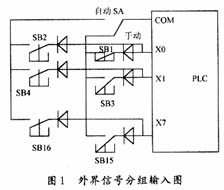
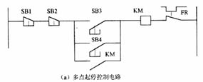
 In the motor control circuit of the multi-point start/stop as shown in Fig. 2(a), the motor can realize the control of starting and stopping at different places. If PLC control is used, the wiring methods of Figures 2(b) and (c) can be used separately. Figure 2 (b) wiring occupies more PLC input points (5 in total), the ladder diagram is also complicated;  Figure 2 (c) wiring, the external input signal is connected in series and input, occupying less PLC input points (2 in total) ), the ladder diagram is also relatively simple.
2.1.3 Input in matrix form In a complex system controlled by a relay output type PLC control system, the number of required PLC input points can be significantly reduced by matrix input. In Figure 3, COM2 at the output is connected to COM1 at the input. Y430, Y4 31, and Y432 are rotated to the "1" state by software, and the state of K1, K2, and K3 is read when Y430 is "1". In the ladder diagram, the normally open contacts of Y430 and X400 should be connected in series as the input amount provided by K1; when Y431 is "1", the state of K4, K5, K6 and the like are read. The diodes in the figure are used to prevent the generation of parasitic circuits. This type of input method is particularly suitable for input elements that do not change often.
2.1.4 Part of the signal does not occupy the terminal. Some functions are simple, involving a narrow input signal, such as manual operation buttons, thermal relay normally closed contacts, etc., they can be set in the external hardware circuit of the PLC, there is no need to be a PLC Input signal.
2.2 Using software functions to achieve cost reduction
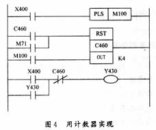
2.2.1 One-point use (1) The start and stop control of a circuit through a counter is usually done by two buttons. When a PLC controls multiple circuits with start/stop operations, it will occupy a lot of input points. If one button is used to start and stop, half of the input points can be saved. The single button start and stop control circuit realized by the counter can be used. Figure 4 shows. 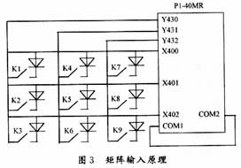
 (2) The circuit realized by the timer is as shown in Fig. 5. When the button X400 is pressed, the output coil Y431 is set to be turned on. The auxiliary contact of Y431 causes the timer T601 to start 2 s. After 2 s, the timer T601 normally closed contact is opened, and the normally open contact is closed. When the button X400 is pressed again, since both X400 and T601 are turned on, the output coil Y431 is turned off by the reset command RST, and the external load is stopped.
(3) realized by shift register 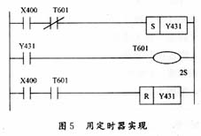
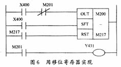 In the circuit shown in FIG. 6, when the button X400 is pressed, the two contacts of the X400 turn on the data input of the shift register and the shift input two terminals, M200 is in the "1" state, and is immediately shifted. To M201, make M201 also "1" state, M201's normally open contact is closed, so that Y431 has output, the external load is turned on, and the normally closed contact of M201 is disconnected. When the X400 button is pressed again, since the M201 normally closed contact blocks the second signal input, the shift signal shifts the "0" state of M200 to M 20 1, making M201 "0". Its normally open contact M201 cuts off the output of the Y431 and stops the load operation. At this point the circuit returns to its original state and waits for the next press of the button.
(4) The pulse output command is also called the differential output command by the pulse output command. The circuit is shown in Figure 7, when the button X400 is pressed. Under the action of the differential pulse output command PLS, the auxiliary relay M300 is turned on for one scan cycle, and its normally open contact turns on the auxiliary relay M100 coil circuit, and the M100 normally open contact is closed for one cycle, under the action of the set command M301 When it is turned on, the M301 normally open contact turns on the output relay Y431 coil, and the Y431 coil outputs a control signal for driving the external load to start the load.
When the button X400 is pressed again, under the action of the differential pulse output command PLS, the M300 normally open contact turns on the M101 coil for one scanning cycle, and the M 101 normally open contact is closed. Under the action of the reset command, the Y431 coil circuit is disconnected. Stop the external load from working. 
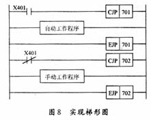 2.2.2 Jump Coil for Manual and Automatic Operation Figure 8 shows the ladder diagram of the manual and automatic operation functions with one input point X401. The X401 is connected to the automatic/manual working mode changeover switch. When the switch points to manual, the X401 normally open contact closes and the jump condition is established. At this time, the program between CJP 701 and EJP 701 will be skipped, so that the automatic working program is not executed. Similarly, when the switch points to automatic, the automatic operation is performed. program. 3 Conclusion In the design process of PLC control system, by using the above method, the utilization efficiency of PLC input/output points can be greatly improved, the actual use quantity of PLC input/output points can be saved, the volume of PLC can be reduced, and the cost can be effectively saved.
SHENZHEN CHONDEKUAI TECHNOLOGY CO.LTD , https://www.szsiheyi.com