USB 3.0 transfer rate is up to 5Gbit/s, and the power bus also has a maximum output current of up to 900mA. Therefore, the prevention of electrical transients and overcurrent faults is extremely important. Designers must carefully select the appropriate thermistor (PTC). And electrostatic discharge (ESD) solutions to ensure signal integrity and reduce the risk of system failure.
Since the release of the Universal Serial Bus (USB) specification in 1996, more than 3.5 billion computer peripherals have been shipped with USB connectivity devices as of 2012. In 2010, when the first devices supporting USB 3.0 specifications were launched, the sales volume reached about one million. In 2012, the number of devices increased to about five million, which shows that the market has grown quite rapidly.
Compared to USB 2.0, USB 3.0 has four additional data channels with transfer rates up to 5 Gbit/s (Figure 1), and the power bus also has a maximum output current of up to 900 milliamps (mA). These new specifications plus wafer size Constant shrinkage has made it more important and complicated to prevent electrical transients and overcurrent faults in circuits, because even small electrostatic discharge (ESD) and short-circuit accidents can cause serious damage to the system at high speeds.
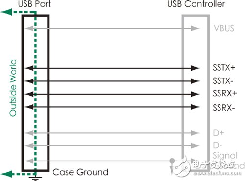
Figure 1 USB 3.0 adds dual differential data pairs to achieve a 5Gbit/s high-speed transfer rate.
Since wafer sensitivity, signal integrity, and system reliability are a concern for system designers, parasitic capacitance, low clamping voltage, and low resistance on USB 3.0 systems are key indicators of circuit protection component selection. Since the USB 3.0 power line allows for more current to pass, the current protector has a lower resistance and becomes critical in ensuring low dropout. The key to a successful design is to master protection technologies such as thermistors (PTCs), varistors, and ESD solutions. This article will explain in detail the design factors that need to be considered.
USB 3.0飙 high-speed circuit protection challenges are more difficult
The most important physical change from USB 2.0 to USB 3.0 is the introduction of two differential data, SSRX+/SSRX and SSTx+/SSTx, and maintains a parallel mode with the existing D-/D+ data bus, which allows data to be transmitted simultaneously at full duplex. Improved USB 2.0 bus can only be a single duplex transmission problem. In addition, USB 3.0 increases the current on the power bus from 500 mA to 900 mA, amplifying the choice of external equipment power supply, eliminating the need for additional power supply options.
Since USB 3.0 introduces additional differential data, which triggers more ESD protection requirements, the way in which separate individual components were protected by separate components in the past is not enough to protect their circuits. The challenge for engineers is to find better ESD and voltage transients. The protection scheme allows the sensitive data line to be protected without increasing the signal distortion capacitance. At this stage, most of the industry adopts new semiconductor array ESD protection devices directly in the data alignment, while protecting the traditional USB 2.0 data lines and USB 3.0 additional data lines.
At the same time, the USB 3.0 specification, 11.4.1.1.1, states that for safety reasons, the host and all self-powered hubs must be overcurrent protected. The hub must detect overcurrent conditions and report them to the USB control software. The overcurrent limiting mechanism must be self-resetting without user intervention, and polymer PTC and solid state switches can be used in one of the methods of overcurrent limiting.
USB 3.0 may require additional overcurrent protection as required by UL60950-1. USB busbar transceiver chips or power management wafers provide partial current limiting, but when the chip does not contain current limiting or additional protection, the circuit The designer must design a current limiting PTC for the power bus.
Installing a polymer PTC on a power bus can limit current in the event of a short circuit and prevent overcurrent damage caused by sudden short circuits. It can also help achieve Section 2.5 of the UL60950-1 standard (limited power supply, Table 2B). It is stipulated that the short-circuit current is limited to less than 8 amps in 5 seconds.
The related USB hub application and USB 3.0 overcurrent protection specification are as stated in 11.4.1.1.1. If the total current of the downstream 超过 exceeds the predetermined value, the overcurrent protection circuit can eliminate or reduce the affected downlink power. . The preset value must not exceed 5 amps and must be greater than the maximum allowable åŸ current or time delay transient current (eg, when powering up, dynamically connected, or reconfigured) to achieve overcurrent protection.
Shoulding USB 3.0åŸ protection, PTC's selection of specifications is very knowledgeable
Figure 2 shows the PTC solution for a multi-turn hub configuration. Table 1 shows the recommended single åŸ and two PTC è” linked PTC components, and lists the required PTCs for the new USB Battery Charging Specification version 1.2. Program.
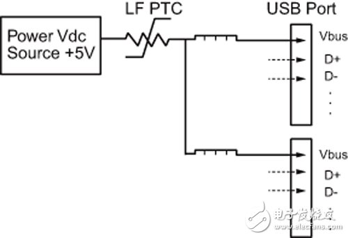
Figure 2 USB 3.0 multi-node configuration diagram

There are several key parameters to consider when selecting PTC for USB protection, including 900 amps for maximum current, operating temperature at PTC position, trigger speed, and DC resistance. All PTCs in Table 1 protect USB 3.0åŸ with a maximum current of 900 mA, and will not trip even at a maximum operating temperature of 60 °C.
Since the temperature change may cause the PTC's trigger rate to drop, this is also an important aspect of the PTC selection process. Designers should consider incompatible USB 3.0 devices when selecting PTC, and load 900 mA current to make PTC There is a maximum available current of more than 900 milliamps at the highest operating temperature, otherwise the PTC may trigger incorrectly.
Each PTC also triggers a short-circuit fault at a current of 8 amps at less than 5 seconds, so it is important to comply with the UL60950-1 limited power specification and to limit the current in the USB 3.0 specification to 5 amps.
The final key parameter for choosing the most suitable PTC is the DC resistance. Since USB 3.0 now offers a maximum current of 900 mA, the power dissipation in the circuit must be further reduced. In addition, the voltage drop across the components of the power bus must be reduced, especially when the circuit's resistor budget is tight.
Overall, the primary goal of choosing a PTC is to ensure that the current device can withstand at least 900 milliamps of current at the highest temperature. Taking the case of setting the worst design temperature of 60 °C as an example, a single-turn application should select a minimum size and support a maximum current requirement of 0.95 amps, as in the first option in Table 1. If a PTC is used to protect two USB 3.0 ports, the third option in Table 1 is a good choice because it maintains 2.19 amps at 60 °C for all safety reasons.
Crystal Box Vape 5500,Crystal Box E-Cigarette 5500 Puffs,Disposable Vape Pen 800 Puffs,E-Cigarette 5500 Puffs
Shenzhen Niimoo Innovative Technology Co., Ltd , https://www.niimootech.com