With two or more independent LEDs, today's drives are able to control the trendy decorative light that can be used in portable systems. Not only is the ILED peak current fully programmable, each LED can be dimmed to any value between 0 and 100% brightness range. In addition, the embedded progressive dimming function, which works in both up and down directions, provides a special illumination sequence that is required by the end customer. This article describes the characteristics of this driver and focuses on progressive dimming based on a typical application. In addition, related software is discussed as a typical example.
Basic analog operation
In general, LED drivers provide a constant current to bias the LEDs under appropriate conditions. If we consider a portable system, the power supply is a battery with an output voltage range of 2.8 to 4.2V (assuming a standard lithium-ion battery). Since the forward voltage of today's low power LEDs varies between 2.8 and 3.5V depending on the bias current and room temperature, an interface is needed to ensure that the LEDs are properly biased during normal operation. This is the purpose of the driver IC, and the first module to consider is the voltage range of the current control system.
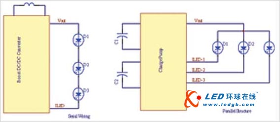
Figure 1 basic LED wiring

Figure 2 Comparison of advantages and disadvantages of serial-parallel links
In this regard, we can consider connecting the LEDs in series or in parallel: these two connections have their own advantages and disadvantages, as shown in Figure 2.
The key point is the ability to independently and dynamically adjust the brightness of each LED in a color application. While it is possible to use a boost structure that uses a switch to connect between each LED to control them, serial alignment is not the preferred solution, and parallel architecture is the easiest to implement.
The charge pump is the DC-DC converter that produces the smallest and most suitable low voltage and EMI problems. On the other hand, using multiple modes of operation (1X, 1.5X, 2X) purely increases efficiency, allowing the system to save as much energy as possible while running in a portable device.
In addition to the DC-DC converter, the second key parameter is the current matching between the LEDs belonging to the common array: the RGB structure cannot accommodate the bias current difference between the LEDs, as these differences translate into color representations in video and image displays. This problem is solved by using a precise set of current mirrors as shown in Figure 3.
To achieve accurate and stable forward bias conditions in the LED, a reference current is generated by an external resistor associated with the constant voltage provided by the bandgap reference. Transistor Q1 associated with operational amplifier U1 produces a constant output voltage at the Vref pin. The external resistor connected between Vref and ground produces a constant current through Q1 and Q2. This current is mirrored and amplified by the Q3~Q7 transistor family. Each current is connected to switches S1~S5 and added by transistor Q8. Finally, transistor Q9 replicates the reference current to LED 1. This configuration is replicated for each LED, and the layout of the chip is carefully analyzed to optimize the match between each LED.