Summary:
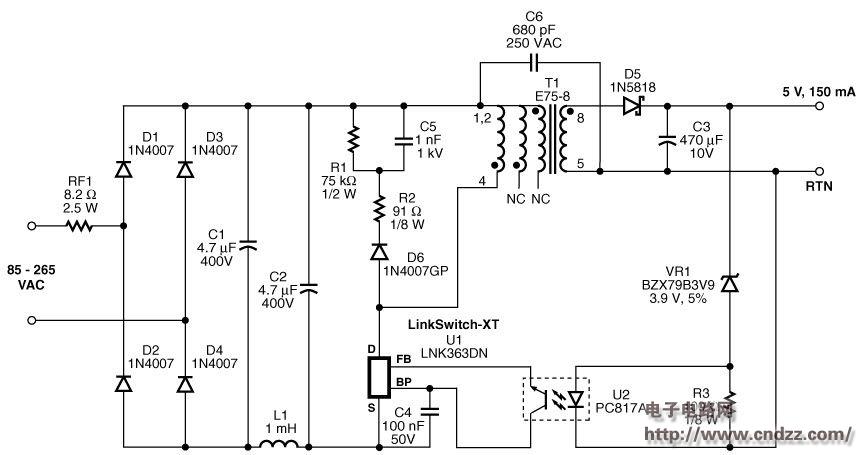
The tamper-proof meter power supply circuit design uses the LNK363DN to generate an isolated output of 5 V and 150 mA. The transformer designed here has sufficient inductance to enable the power supply to provide the required power. Even if someone uses a strong external magnetic field to saturate the core in an attempt to tamper with the meter, the power supply will not be affected.
Tamper-proof meter power supply design features
- Low cost and low component count
- Enhanced tamper-proof protection with iron powder core material
- Can still work normally under the interference of external magnetic field
- Low working flux density (400 Gauss), reduced core loss (<40 mW)
- High efficiency (up to 58% at full load)
- Efficient use of the available power at the input (the limit of the IEC10362 standard is 2 W, 10 VA)
- Fully extend the maintenance time
- The time-consuming electrical energy is stored in the input capacitor
- No need for large output capacitors or a second higher output voltage
- Conforms to EN55022B conducted EMI limits, EMI margin >6 dBmV
Circuit diagram of 0.75W tamper-proof meter power supply
See the uploading documentation for details (click to download)
China Wifi Antenna,High gain WiFi Antenna.Factory Price WiFi Antenna
WIFI Antenna.2.4G Antenna.5.8G Antenna.Wifi Outdoor Antenna.Wifi Antenna Long Range 50 Km
Yetnorson Antenna Co., Ltd. , https://www.yetnorson.com