Design of RFID reader based on MCU + FPGA mode
Radio frequency identification technology RFID is a non-contact automatic identification technology. Its basic principle is to use radio frequency signals and spatial coupling (inductive and electromagnetic coupling) transmission characteristics to achieve automatic identification of the identified object. The radio frequency identification system generally consists of two parts , RF tag (Tag) and RF reader (Reader). In RFID applications, the electronic tag is attached to the identified object. When the identified item with the radio frequency tag enters the readable range of the reader, the reader automatically reads the agreed information in the radio frequency tag in a contactless manner Take it out, so as to realize the function of automatically identifying items and collecting item logo information.
RFID technology has broad application prospects in industries such as production, retail, logistics, and transportation. In order to solve the problem of visual dynamic monitoring of logistics materials in the process of request, transportation, distribution, etc., RFID technology is widely used in the field of military logistics. The basic usage is to install and deploy RF reader network in warehouses, docks, stations, and important traffic intersections Nodes, when military materials equipped with radio frequency tags pass through, relevant material information, transportation information and safety information are automatically collected and uploaded, which realizes the visual monitoring of the logistics material supply chain.
1 RF reader function requirements
The radio frequency reader is used to read and write all kinds of information stored in the radio frequency tag at a long distance. Consider the ability of material monitoring during transportation. The RF reader is required to adapt to the field working environment. Designed reliable anti-interference and protection measures The main performance requirements of RF readers are as follows:
(1) Omnidirectional radio frequency tag identification, reading and writing functions;
(2) High-speed data processing capability:
(3) Diversified data communication interface design:
(4) It can adapt to the rapid reading of radio frequency tags under high-speed motion:
(5) When used in AC / DC power supply, consider vehicle-mounted design;
(6) Perfect ground anti-interference, anti-lightning and surge measures;
(7) Software middleware development, configuration, and operation are convenient and fast.
2 Structure of the reader
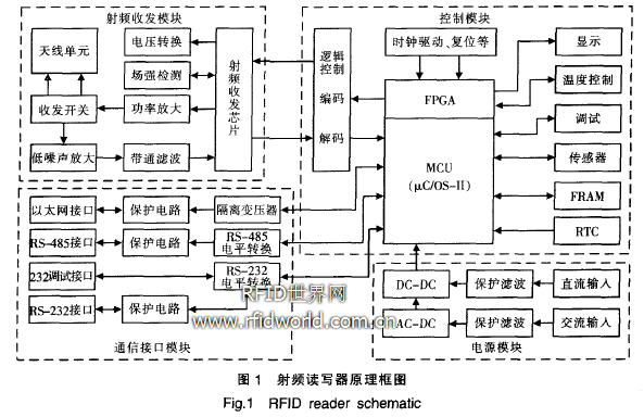
According to functional requirements, the design of RF readers is mainly composed of five parts: control module, RF transceiver module, antenna unit, communication interface module and power module. As shown in Figure 1. The control module is based on NXP's LPC23 series high-performance ARM7 embedded microcontroller (MCU). Built-in μC / OS-II multi-task operating system. It constitutes a real-time multi-task high-speed data processing platform, and realizes functions such as radio frequency control, air protocol, data storage, Ethernet protocol and serial port communication through peripheral circuits.
The radio frequency reader is between the radio frequency tag and the software middleware, and is the main bearer of the protocol stack of the data link layer and the media access layer. Requires high-speed, large-capacity data processing capabilities and real-time multi-task control capabilities. To this end, the reader designed an embedded real-time multi-tasking processing platform composed of a 32-bit high-speed MCU + FP-GA + IxC / OS-II multi-task operating system. The platform is reliable, stable, and has the characteristics of rich peripheral interfaces and good scalability. It effectively guarantees the rapid collection, processing and exchange of information. The RF transceiver module completes the functions of carrier generation and air signal modulation / demodulation, and the two antennas of the antenna unit are arranged perpendicular to each other. Connected to the RF transceiver circuit through a small RF cable. Realize the function of reading and writing field devices to send and receive RF signals in all directions. The communication interface module provides three communication interfaces: RS232, RS485 and Ethernet. The power module provides reliable AC and DC power supply guarantee for the operation of software and hardware systems.
3 hardware system design
3.1 MCP860T embedded processor based on PowerPC system
In the hardware system design of the RF reader, the performance of the embedded microprocessor is undoubtedly a key factor affecting the performance of the entire device. According to the function and performance requirements of the system, after demonstrating and comparing, the MCU uses NXP's 32-bit LPC2387 ARM7 microcontroller, the best operating frequency reaches 72MHz, can achieve high-speed data transmission and transmission, the system has a strong fast response capability . LPC2387 is a controller with abundant peripheral resources. Integrated 512KB Flash Rom. 98KB SRAM. The hardware can encrypt the program code space, maximize the protection of the intellectual property rights of developers, and ensure the security of military applications. The controller integrates 15 serial communication interfaces in 8 categories. Including 1 10 / 100Mb / s Ethernet. Industrial PHY. 1 USB2.0 full speed (12Mb / s) data interface, 2 CAN interfaces, 4 UART controllers (UART1 conforms to 16C550 industry standard, UART3 supports IrDA mode), 3 high-speed I2C buses, the highest data transmission speed is 400kb / s. 1 way PS. 1 way SPI and 2 way buffered SSP bus rich connection VI meets the needs of data communication and peripheral expansion: LPC2387 supports SD / MMC interface, provides a guarantee for the storage of a large amount of configuration information and temporary material information storage. The temperature is -40 ~ C ~ + 85 ~ C, and the LQFP100 package meets the requirements of wide operating temperature and small size for military applications. In addition, LPC2387 provides watchdog timers, four 32-bit timers / counters and abundant GPIO resources.
3.2 Using FPGA to achieve complex logic control FPGA uses LatTIce's LFXP3C logic device, which mainly completes 6 functions: realizes the interface with the CPU, performs system interrupt processing, realizes multi-channel data encoding and decoding, and completes the RF board switch. The control, ADC control part and LED control part adopt FPGA to realize the digital circuit codec function. Compared with the software codec, the reliability of the system is greatly improved.
3.3 Communication interface and protective measures
There are three types of communication interfaces for RF readers: Ethernet, RS-485 and RS-232. In order to ensure reliable data transmission, the equipment adapts to the field environment, and various interfaces are designed with protection circuits.
The protection circuit of the Ethernet interface is divided into two levels of protection: discharge tube and TVS array chip, which can protect against the impact of lightning strikes and surges on the network isolation transformer. The use of the TVS array chip in this circuit is mainly due to the TVS diode junction capacitance designed inside the chip Smaller. Can greatly reduce the impact on high-speed network data
RS-232 and RS-485 protection circuits are divided into three levels of protection: self-recovery fuses, discharge tubes and TVS diodes, which can protect against overcurrent, lightning strikes and surges.
3.4 Reliable power supply circuit design
The power module provides power supply for each part of the internal circuit of the reader. The reader has two power supply modes: AC and DC. The AC power circuit is designed for wide voltage (90 ~ 260V) input. The DC voltage input range: 12 ~ 24V. Wide range of adaptation. To improve the reliability of the system. The power module selects mature AC / DC and DC / DC.
The power supply module filters, reduces, and stabilizes the AC and DC power supply externally connected. The AC power supply and the DC power supply are all provided with a varistor, a ceramic gas discharge tube, and a power filter. The varistor and ceramic gas discharge tube mainly play the role of overvoltage protection, and the power filter can filter the high-frequency interference signal of the power supply to ensure that the system can still work normally in the harsh power supply environment. The transient voltage protection circuit can effectively protect the unit circuit of the reader.
3.5 Design of antenna diversity technology
The design of the low-frequency receiver in the RF reader uses antenna diversity reception technology in two mutually perpendicular directions, so that the RF tag can be reliably activated when the reader enters the excitation magnetic field from any direction. Channel diversity reception and transmission technology ensures that the reading area has no direction and no blind area. These two antenna diversity technologies have successfully solved the problem of multipath effect of data transmission and reception under the condition of high-speed movement of tags, effectively improved the accuracy of identification, and realized the high-speed dynamic collection of material information during transportation.
4 Software system functions
The software system adopts μC / OS-II embedded operating system with open source code as the management platform. With strong stability and safety, the structure is compact. The software system has also taken many security technical measures, including access control for reading and writing, protected subsystems, audit trail, core authorization, etc. Provide users with the necessary security guarantees. The functions provided by the RF reader and the control function system are shown in Figure 2.

5 Conclusion
This paper presents a design scheme of RF reader based on MCU + FPGA. This solution has the characteristics of high data processing speed, rich communication and control interfaces, and easy software development and configuration. The military radio frequency identification reader developed by this has passed the identification of the relevant departments. And the application practice proves that the operation of the product is stable and reliable.
Semi-Round Sensor Automatic Dustbin
Stainless Trash Can,Semi-Round Sensor Automatic Dustbin,Semi-Round Series Sensor Dustbin,Semi-Round Sharp Sensor Dustbin
NINGBO ZIXING ELECTRONIC CO.,LTD. , https://www.zixingautobin.com