FAN100 provides a design scheme of automobile instrument based on CAN (Controller Area Network) bus. The instrument uses the CAN bus to make it a part of the body network, and reads engine speed, water temperature and other information in accordance with the SAE J1939 protocol. The instrument can also receive and display the signals of the sensor such as vehicle speed, fuel quantity, oil pressure, brake air pressure, etc., and provide the driver with real-time vehicle operating conditions. The designed instrument is mainly used in heavy transport vehicles and other fields. The test results conducted in a heavy vehicle factory show that the instrument can meet the requirements of data reliability and real-time performance.
1 CAN bus and SAE J1939 protocol
1. Brief introduction of CAN bus and SAE J1939 protocol
The FAN100CAN bus belongs to the field bus category. It was developed by the German Bosch company in the early 1980s to solve the data exchange between many control and test instruments in modern automobiles. It is a serial that effectively supports distributed control or real-time control. Communications network. The CAN bus has strong real-time communication, and the data transmission rate can be as high as 1 Mb / s. The communication medium can be twisted pair, Coaxial Cable, or optical fiber, which can be easily connected through standard connectors. The data communication of CAN bus has outstanding reliability, real-time and flexibility, and it is the most widely used automobile bus at present.
The FAN100SAE J1939 protocol is a vehicle network serial communication and control protocol issued by the American Society of Automotive Engineers SAE (Societv of AutomoTIve Engineer) with CAN2.0B as the core network protocol. J1939 was developed with reference to the 7-layer benchmark reference model defined by ISO's open data interconnection model. The agreement clearly stipulates the address configuration, naming, communication method and message transmission priority of the ECU inside the car, and makes a detailed description of the specific ECU communication inside the car. It uses multiplexing technology to provide a standardized high-speed network connection based on the CAN bus for various sensors, actuators and controllers on the car, and achieves high-speed data sharing between in-vehicle electronic devices, effectively reducing The number of electronic wiring harnesses improves the flexibility, reliability, maintainability, and standardization of the vehicle's electronic control system, and maximizes the excellent performance of CAN.
1.2 SAE J1939 data frame format
The FAN100SAE J1939 data frame is based on PDU (protocol data unit) as a unit, which is composed of priority (P), reserved bits (R), data page (DP), PDU format (PF), PDU details (Ps), source address ( SA) and Data Field (Date Field) and other 7 fields. The PDU except the data field corresponds to the 29-bit identifier of the CAN extended frame. PS is an 8-bit segment, and its definition depends on the PF value. If the PF value is less than 240, PS is the target address (DA). If the PF value is between 240 and 255, PS is the group extension (GE).
Some CAN data frames of FAN100 are not defined in PDU, including SOF, SRR, IDE, RTR, control field part, CRC field, ACK field and EOF field. These fields are defined by CAN, and SAE J1939 is not modified.
2 CAN bus car instrument design
2.1 Overall design of the instrument
FAN100 The automotive instrument system consists of three modules: data acquisition, processing and display. Among them, the data collection module is responsible for receiving various data of the vehicle and sending the data to the microprocessor after preprocessing. Sensor signals such as analog signals, pulse signals, and switching signals are collected at each sensor, and then sent to the microprocessor after voltage division, filter shaping, and photoelectric isolation. The CAN bus data such as engine speed, water temperature and fault code are sent to the CAN bus through the engine CAN module, and then received through the CAN transceiver. After receiving the required data, the microprocessor processes the data according to a predetermined algorithm and outputs the processing result. The display module includes pointer, LCD and various signal lights. The microprocessor outputs the results of engine speed, vehicle speed, etc. to the motor driver. The driver drives the stepper motor to rotate, thereby driving the pointer display; the microprocessor directly drives the LCD display and the LED light on and off. The structure of automobile instrument system is shown in Figure 1.

According to the overall analysis of the car instrument, FAN100 is composed of three sub-dial, the left sub-dial displays engine speed, oil quantity and other data, the right sub-dial displays vehicle speed, oil pressure and other data, the middle sub-dial is used to place LCD display Screen and various indicators. The pointers of the instruments are all driven by stepper motors. In the various data received by the instrument, the engine speed, water temperature and voltage are obtained from the CAN bus, and the vehicle speed, oil quantity, air pressure and oil pressure are obtained from various sensors. 2.2 System hardware design
FAN100 instrument adopts Luminarv company's LM3S2948 processor. This is a microprocessor based on ARMCortexM3 core, using 32-bit RISC, embedded CAN controller, analog-to-digital converter (ADC), analog comparator and other functional modules, reducing peripheral circuits and reducing system design costs. The built-in CAN module of the LM3S2948 processor facilitates the transmission of CAN bus data, and at the same time makes the communication of the instrument easy to realize and improves the reliability. Its built-in CAN module has the following characteristics: supports CAN 2.0B protocol and supports message transmission of extended frames in accordance with SAE J1939 protocol: bit rate can be up to 1 Mb / s; has 32 message objects, each object has its own Identifier mask code; contains maskable interrupts, for time-triggered CAN (1TrCAN) applications, you can choose to disable the automatic retransmission mode; seamlessly connect with the external CAN PHY through the CANOTx and CANORx pins; with programmable F1F0 mode.
FAN100LM3S2948 microprocessor has the characteristics of fast operation speed, small power consumption, small size and low price. Its CAN controller module characteristics fully meet the application requirements of CAN bus automotive instruments. The processor has powerful processing capabilities, and can reflect vehicle information in real time under various working conditions of the vehicle. At the same time, the processor has a large expandable space, which is conducive to subsequent development.
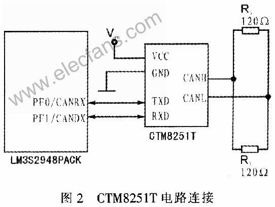
Because FAN100 has a built-in CAN controller module in LM3S2948, it only needs an external CAN transceiver to receive bus data. This instrument chooses CTM8251T as CAN transceiver. CTM8251T is a universal CAN transceiver with isolation, which integrates all necessary CAN isolation and CAN transceivers. The device can be connected to any CAN protocol controller to achieve the CAN node transceiver and isolation functions. The device has a small design and high integration, which can replace the traditional CAN transceiver and its peripheral circuits, reducing the complexity of the circuit and reducing the design cost, as shown in Figure 2.
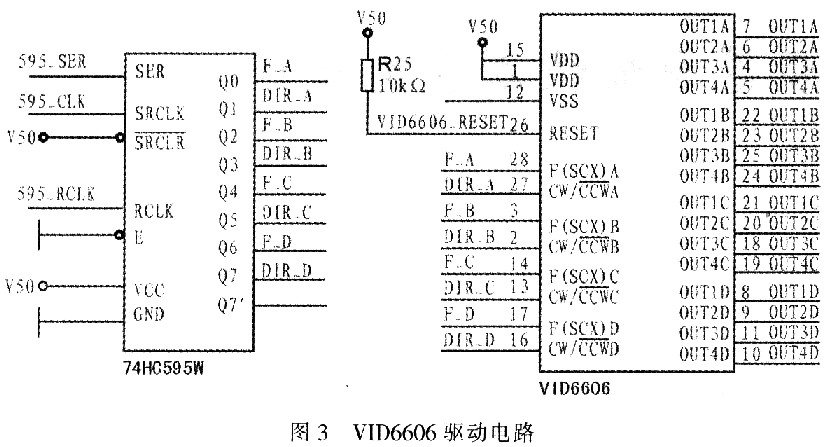
FAN100 instrument uses VID6606 driver to drive the stepper motor. Each VID6606 can drive 4 stepper motors at the same time. Input the pulse sequence F (SCX) at its frequency control end to control the output end to make the output shaft of the stepper motor rotate in microsteps, each microstep motor output shaft rotates by 1/12 (°), the maximum angular speed can reach 600 (°) / s. The motor driver has the following characteristics: hardware microstep drive, simple and easy to use, the motor only needs two control terminals of speed F (sex) and direction (CW / CCW), all input pins have interference filters, wide operating voltage, Low electromagnetic interference radiation. The instrument panel pointer is driven by a VID-29 motor. The motor has a gear system with a reduction ratio of 180/1, which can directly and accurately convert digital signals into analog display output. The motor has a high display accuracy, and its step angle can reach a minimum of 1/2 (°). Figure 3 shows the VID6606 driving instrument circuit.
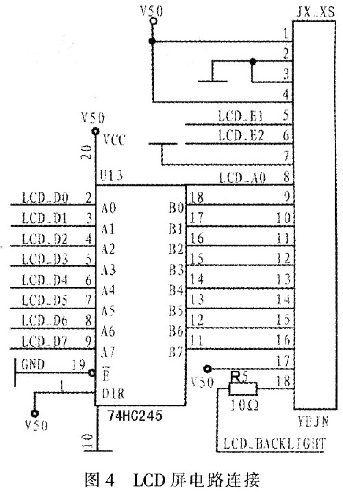
FAN100 uses the LCD to display the time, fuel consumption and the name of the fault when the fault occurs. The signal sent by the processor is first amplified by 74HC245 power, and then sent to the LCD screen F2000LCD for display. The LCD circuit is shown in Figure 4.
2.3 System software design
The software design of FAN100 system is divided into 4 modules including main program, CAN communication, data acquisition and processing and data display. The main program module handles data processing by calling each sub-module program: the CAN communication module is responsible for sending and receiving data; the data collection and processing module completes the collection and calculation of various types of data; the data display module combines vehicle speed, oil pressure, and signal lights, etc. The information is displayed on the meter.
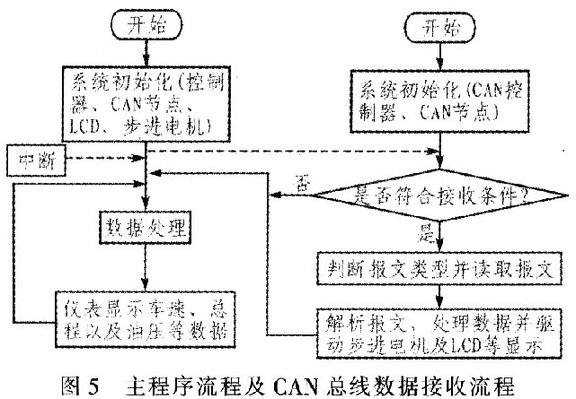
FAN100 Figure 5 is the system main program flow, the system main program flow is divided into: 1) system initialization. System initialization mainly includes initializing the system clock, CAN node, LCD liquid crystal screen, stepper motor, etc., and enabling CAN interruption, setting the CAN mask code and acceptance code. CAN node initialization is mainly to initialize the CAN controller and interrupt the CAN controller: 2) Read the sensor and CAN bus data, and drive the pointer and LCD display, while waiting for CAN to receive the interrupt. 3) CAN receive interrupt is generated, enter the receive interrupt subroutine to read data. Determine whether the data meets the data reception conditions, and if so, receive the data. This process compares the received 29-bit identifier with the acceptance code and mask code bit by bit. Only when the corresponding bit of the identifier is the same as the corresponding bit of the acceptance code, the system starts to receive data. 4) The processor parses the received message, extracts the required data and processes it. The processor processes and calculates the data from the sensor and the data read from the CAN bus to obtain the corresponding pointer driving parameters, calculate the pointer rotation angle, and calculate the pointer rotation speed according to the parameters of the initialized stepper motor. The pointer rotation speed is proportional to the speed of the corresponding parameter change. At the same time, the mileage of the vehicle is calculated and added to the total distance. 5) The processor sends a set of pulse sequences containing vehicle operating conditions to the stepper motor driver. The driver drives the stepper motor to rotate in microsteps, indicating the corresponding engine speed, vehicle speed, water temperature, oil pressure, etc .; the processor will Data containing information such as the total distance of the vehicle is sent to the LCD controller. The controller controls the LCD to display the corresponding total distance. The processor changes the corresponding I / O pin status and directly lights up / off the corresponding indicator light.
2.4 Fault display
FAN100 The instrument can receive the fault code from the CAN bus and analyze the fault code. After comparing with the pre-written fault code, the corresponding fault information is found and displayed on the LCD screen. Each type of data has a specific data frame ID, and the system determines the location of the fault based on the frame ID. If a single-frame failure is received, the system extracts the total number of bytes and total packets; if it receives a multi-frame failure, the system continuously extracts the fault diagnosis message to a specific byte, and then searches according to the fault code Fault type.
3 Conclusion
Based on the study of CAN bus and SAE J1939 protocol, the CAN bus automotive instrument is designed. This design makes full use of the functions of LM3S2948 and VID6606, which greatly reduces the design and cost of system peripheral circuits. The results of multiple actual vehicle tests show that, compared with conventional instruments, the CAN bus instrument has the following advantages: strong anti-interference ability and high transmission rate, which can ensure the effective, rapid and stable transmission of data; reduce body wiring, hardware program software implementation It simplifies the design and reduces costs; timely and intuitively view vehicle failures; CAN bus forms the entire vehicle into a network system, which can increase the flexibility of the system, easily add equipment, and expand the space that can be developed.
Single Core Power Cable,Single Core PVC Insulated Cable,Flexible Single Core Power Cable,XLPE Single Core Power Cable
Huayuan Gaoke Cable Co.,Ltd. , https://www.bjhygkcable.com