In recent years, due to the advantages of high torque current ratio and high efficiency of permanent magnet synchronous motor (PMSM), it has been widely used in servo systems. With the increasing demand for quick positioning and simple commissioning, higher requirements have been placed on the control technology of servo drives. Therefore, the control technology of the servo system composed of PMSM has become a research hotspot. In view of the disturbances such as load torque disturbance and parameter perturbation in the permanent magnet synchronous motor system, people adopt different ideas to solve it. On the one hand, based on the classic PID control, the online adjustment of parameters is studied. On the other hand, advanced control theories such as intelligent control technology, sliding mode variable structure control, predictive control, and observers have also been extensively studied.
This paper proposes a dual-loop control method based on auto disturbance rejection control for PMSM position control. ADRC is introduced into the PMSM servo system control, and the second-order nonlinear ADRC is used to realize the composite control of position and speed. From the control structure, the traditional position, speed, and current three-loop cascade control is changed to position current double-loop control, which can be simplified Servo system debugging process and improve dynamic response speed. On the basis of establishing the mathematical model of the servo system, the design methods of the second-order nonlinear ADRC of the position loop and the first-order linear ADRC of the current loop are given, and the dynamic response and anti-disturbance performance of the servo system are studied.
1. ADRC anti-interference mechanismThe reason why ADRC can effectively improve the anti-interference ability of the system is to extract the interference signal from the controlled output and perform disturbance compensation in the control law. In order to observe the disturbance in the system, it is necessary to design an expanded state observer, which uses the actual output of the system y and the control quantity u to track and estimate the state variables and disturbance quantities of the system in the form as follows:
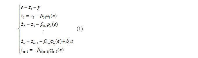
Where: z1, z2, ..., zn are the observed values ​​of the state variables; zn + 1 is the estimated disturbance value; β01, β02, ..., β0 (n + 1) are the observer parameters.
When φi (e) is a linear function, ESO is a linear observer; while φi (e) has a nonlinear characteristic, it is a nonlinear observer, and the state variables and disturbance values ​​of the system can be accurately estimated by appropriately selecting the parameter β.
2. Servo system auto disturbance rejection control1. Disturbance analysis of servo system
In the synchronous rotating coordinate system, the electromagnetic torque Te can be expressed as
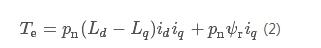
In the formula: pn is the number of motor pole pairs; iq and id are the AC and DC axis current; Lq and Ld are the AC and DC axis inductance; ψr is the rotor flux linkage. The equation of motion is
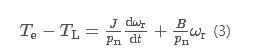
Where: TL is the load torque; ωr is the electrical angular speed; J is the rotational inertia; B is the viscous friction coefficient.
There are Ld = Lq in surface-mounted synchronous motors. Combining equations (2) and (3), a second-order system can be established with the electrical angle θ and the rotor electrical angle speed ωr as variables:
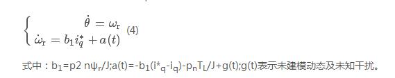
In the above second-order system with iq as input and electrical angle θ as output, a (t) can be regarded as the total disturbance of the position control loop, including q-axis current loop control error, load torque, rotor flux linkage, rotational inertia and other parameters Changes, unmodeled dynamics represented by g (t), etc.
When a disturbance occurs, the traditional feedback control method that relies on errors can only be adjusted after a position or speed deviation occurs, and there must be a certain degree of lag. In order to achieve high-performance control, it is necessary to quickly suppress the influence of these disturbances on the position control. In this paper, the disturbance rejection in the system is estimated and compensated by the auto disturbance rejection controller to improve the anti-disturbance ability of the system.
2. Displacement planning
The dynamic response of the servo system is too fast, which may cause overshoot in positioning. In order to suppress the overshoot in the process of position tracking, this paper uses the tracking differentiator composed of the discrete speed control synthesis function fhan to perform displacement planning. The synthesis function fhan expression is as follows:
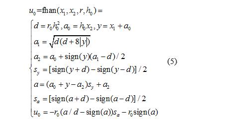
Where: x1 and x2 are input variables; r and h0 are adjustment parameters; u0 is the function output value; others are intermediate variables.
Therefore, the displacement planning is shown in equation (6), the parameter h0 is taken as the calculation cycle of the displacement planning, and the speed of the position command tracking is adjusted by the unique parameter r0. This displacement planning method can not only track a given position command, but also suppress the noise in it.
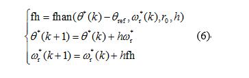
In the formula: θref is the given position; θ * (k) and ω * r (k) are the actual position command and speed command of the kth operation cycle in the position tracking process respectively, k≥0, and θ at steady state * = θref; h is the calculation cycle of displacement planning; r0 determines the tracking speed.
3. Compound position and speed control based on auto disturbance rejection
To realize ADRC, the disturbance in the system needs to be observed. Combined with equation (4), the electrical angle θ of PMSM and the given value of the q-axis current i * q are used to dynamically estimate the position and disturbance of the servo system. The third-order extended state observer It can be expressed as
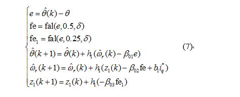
Where: θ ^ (k) θ ^ (k) and ω ^ r (k) ω ^ r (k) are the electrical angles of the kth calculation cycle
The estimated values ​​of degree θ and electrical angular velocity ωr, k≥0; e is the observation error; fal is the nonlinear function; z1 is the observed value of the disturbance; β01, β02, β03 are the observer coefficients; h1 is the position loop control period.
among them,
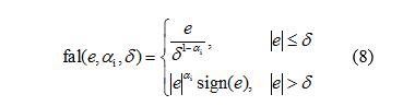
Where: δ is the error threshold; sign is the sign function; αi is the parameter.
The fal function has the characteristics of "large error, small gain; small error, large gain"; δ represents the linear interval, the purpose is to avoid high-frequency chatter caused by high gain when the error is small.
The implementation block diagram of the above-mentioned nonlinear third-order extended state observer is shown as position ESO in FIG. 2. The disturbance z1 of the position loop is estimated in real time by the position information θ, such as load torque change, system inertia change etc. The method is compensated into the system to improve the interference suppression ability of the system.
In order to make the position loop have higher anti-disturbance adjustment efficiency, the error feedback law adopts the nonlinear control law of the following formula (9), including the feedback channel of position error and speed error and the feedforward channel of disturbance z1. A loop is used to realize the composite control of position and speed. When designing the position loop, it is not limited by the bandwidth of the speed loop, which not only simplifies the control structure, but also facilitates the parameter setting of the system.
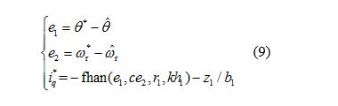
In the formula: b1 = p2 nψr / J; c, r1 and k are control parameters; h1 is the position loop control period; fhan function see formula (5) for details.
The parameter r1 is the control gain. When the system error is large, the value of r1 is increased appropriately, and the speed of the error tends to zero. Introduce the parameter c before the speed error to adjust the strength of the speed control effect in the composite control. Figure 1 shows the contours of the fhan function when r = 3.5, h1 = 0.001, k = 1000, and c take 1 and 6, respectively. It can be seen that as the parameter c increases, the linear adjustment area of ​​the output of the fhan function decreases, increasing the effect on speed control. But this does not mean that the larger the value of r1 and c, the better, because excessively large control gain may cause high-frequency chattering at steady state. In this case, it is necessary to increase the value of k appropriately.

Fig.1 Contour of fhan function with r = 3.5 and different c values
Therefore, the position and speed composite control block diagram based on nonlinear auto-disturbance control is shown in Figure 2. The given position θref passes through the displacement gauge
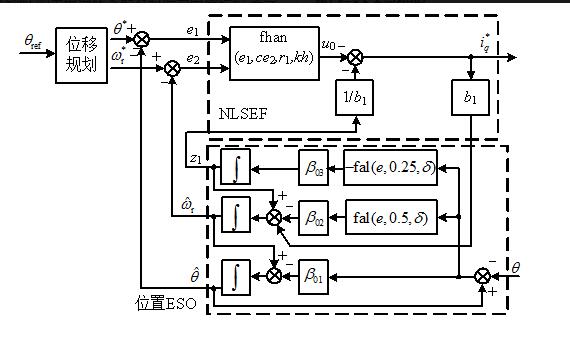
Figure 2 Structure diagram of combined control of position and speed
The plan generates position and velocity references, and operates with the estimated value of the expanded state observer, and after a nonlinear control law, the given value of the q-axis current is obtained.
Therefore, the position and speed composite control block diagram based on nonlinear auto-disturbance control is shown in Figure 2. The given position θref generates position and velocity reference through displacement planning, and operates with the estimated value of the expanded state observer, and after a nonlinear control law, the given value of q-axis current is obtained.
4. Current loop auto disturbance rejection control
In the servo system, when the load torque is disturbed, if the current loop cannot adjust the electromagnetic torque in time, it will cause a large deviation in position and have a great impact on the performance of the servo system.
Based on rotor field-oriented vector control, when id = 0 control is used, the q-axis equation can be expressed as
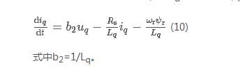
When the load changes, it will cause the fluctuation of the rotation speed ωr. In equation (10), the change of -ωrψr / Lq can be regarded as the interference term, and the perturbation of the parameters of the resistance Rs and the inductance Lq can also be regarded as Disturb. Therefore, the first-order ADRC algorithm is adopted to suppress the interference term caused by the rotation speed in a timely manner, so that the influence on the position loop is small. In order to facilitate parameter design and engineering tuning, the observer is taken as a second-order linear state observer:
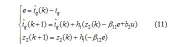
Where: i ^ q (k) i ^ q (k) is the estimated value of the q-axis current iq of the kth calculation cycle,
k≥0; z2 is the observed value of disturbance; β11 and β12 are the coefficients of the current observer; hi is the calculation cycle of the current loop.
As mentioned earlier, the performance of ESO has a greater impact on disturbance observation. An effective method for selecting linear ESO parameters is to use the concept of bandwidth [20]. The bandwidth of the current loop is taken as ωi, and the characteristic polynomial of the current loop ESO is s2 + β11s + β12. In order to estimate the state and disturbance better, make it the ideal characteristic equation form (s + ωi) 2, so the parameter
The number β11 = 2ω, ωiβ12 = ω2iωi2.
The current loop uses a linear error feedback rate, as follows:

Where Kpi is the current control gain.
Therefore, the block diagram of the first-order ADRC of the current loop is shown in FIG. 3. The expanded state observer gives the disturbance value z2 of the system while observing the current, which is compensated to improve the system's ability to resist disturbance.
The structure of PMSM double-loop servo drive system based on auto disturbance rejection control is shown in Figure 4. Using i * d = 0 control mode, the position second-order ADRC controller adjusts the torque current set value i * q, the torque current first-order ADRC controller and excitation current PI regulator adjust the corresponding d, q-axis stator voltage Desired point.
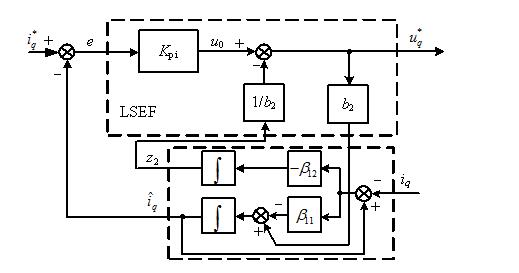
Figure 3 Current iq first-order ADRC structure diagram
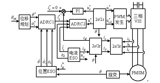
Figure 4 Control block diagram of double-loop servo system based on auto disturbance rejection control
3. Simulation ResearchThe parameters of the permanent magnet synchronous motor for simulation and experiment are as follows: rated speed nN = 2000r / min; stator resistance Rs = 0.212Ω; cross-axis and inductance Ld = Lq = 3.2mH; rotational inertia J = 0.0176kg • m2; pole pair pn = 4; rotor flux ψr = 0.199T. The DC bus supply voltage is 150V, the current loop control period is 200μs, and the position loop control period is 1ms.
1. Performance verification of the expanded state observer
When the given position θref = 251.2rad, the simulated waveforms of position and speed are shown in Figure 5. It can be seen that the system can accurately observe the position and rotation speed during the steady state and dynamic tracking process, indicating that the designed expanded state observer has high observation accuracy.
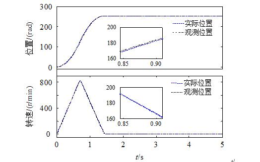
Figure 5 Simulation waveform of position and speed during positioning
2. Verification of the influence of position loop parameters on control performance
When the given position θref = 251.2rad, the position loop parameter r = 3.5, and the simulation waveform when c takes 1 and 6, respectively, is shown in Fig. 6. When c = 1, the maximum value is 251.52rad, the system has overshoot, and when c = 6, there is no overshoot and the response time is shorter, as can be seen from the enlarged waveform when the speed drops, the speed tracking characteristic when c takes 6 Better, verified the theoretical analysis in Section 2.3, showing that the introduction of the control parameter c can change the control effect of the nonlinear feedback control law, and the control performance of the system can be improved by choosing an appropriate value.
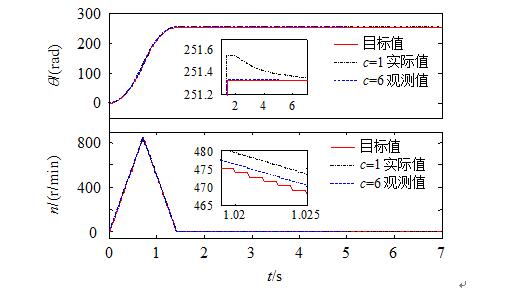
Figure 6 Simulation waveform of position tracking with different values ​​of parameter c
3. Anti-load torque disturbance
The simulation waveform of sudden load during dynamic tracking is shown in Figure 7. The given position θref = 251.2rad, a sudden load of 5N • m at 1s, the maximum speed drop is 20r / min, the given speed is tracked after 40ms, and there is no obvious fluctuation in the position.

Figure 7 Simulation waveform of sudden application of 5N • m load during dynamic tracking
The waveform of sudden load when the system is steady state is shown in Figure 8. When the load of 5N • m is suddenly added at 3s, the maximum speed drop is 18.7r / min, the adjustment time is about 10ms, and there is an error of 0.3rad at steady state. The dynamic and static simulation results show that the system is still stable when the load is suddenly applied, and it has good speed. It proves that the proposed control algorithm has strong ability to resist load disturbance.
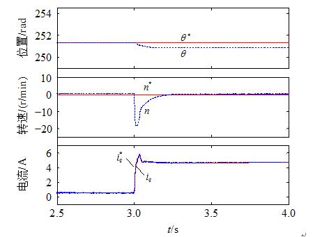
Figure 8 Simulation waveform of sudden application of 5N • m load at steady state
4. Robustness of the system when the motor parameters are mismatched
In the design of the current loop auto-rejection controller, the parameter b2 = 1 / Lq exists in the observer, so the robustness of the system is verified when there is an error in the inductance Lq. Figure 9 shows the simulation waveform of the position tracking process when the parameter Lq used in the control is 50% and 200% of the ideal value. The results show that the system is still stable even under the conditions of large deviations in the inductance. The expanded state observer can still observe the current iq very well, and can follow the change of the given value of the position very well, showing good resistance. The ability to change parameters.
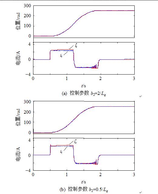
Figure 9 Simulation waveform of positioning when there is an error in the Lq parameter
4. Experimental resultsIn order to further verify the proposed control strategy, the experiment was performed on the dSPACE platform, and the experimental data was saved through the supporting ControlDesk host computer software.
Figure 10 shows the experimental waveform when the given position θref = 251.2rad. It can be seen that during the positioning process, both the position and the speed can follow the target value well, and the steady-state error is 0.4 rad.
Figure 11 shows the sudden load change at a given position θref = 251.33rad
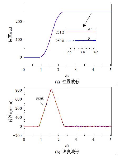
Figure 10 Experimental waveforms of position and speed during positioning
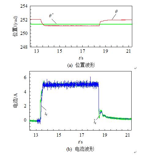
Figure 11 Experimental waveform of sudden load change
Experimental waveform. At 13.5s, a 5N • m load torque disturbance was suddenly applied from no-load for 5s. The error at no-load is about 0.6rad, and the error after loading 5N • m is 0.2rad. The system is still stable.
Figures 12 and 13 give the experimental waveforms under no-load conditions when the parameter Lq used in the controller is 50% and 200% of the ideal value, respectively. Even if different inductance values ​​are used and the motor parameters are mismatched, the current iq is slightly different, but all achieve a good position tracking effect. At the same time, it can be seen from the figure that when the steady state is finally reached,
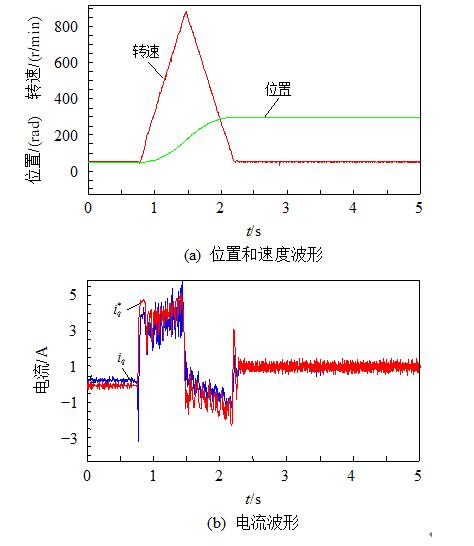
Figure 12 Control parameter b2 = 2 / Lq positioning waveform
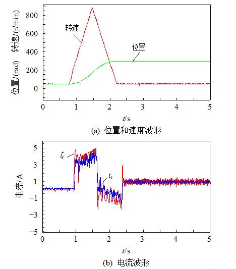
Figure 13 Control parameter b2 = 0.5 / Lq positioning waveform
iq eventually stabilizes at around 1A instead of 0. This is because the motor speed is close to zero at steady state, but the position ESO is still being observed. At this time, because it is still in the dynamic adjustment process, the static friction torque of the motor is not The modeling information is estimated as disturbances outside the ideal model and compensated to the given value of the current loop i * q, so that iq eventually stabilizes around 1A.
The above experimental results show that the proposed dual-loop control method based on auto-disturbance control is correct and improves the system's ability to resist load torque disturbances, while still having strong robustness when the motor parameters are mismatched.
V. ConclusionIn this paper, from the perspective of anti-interference of the servo system, the auto-disturbance control structure of the double-loop position current is proposed according to the ADRC mechanism, and the second-order nonlinear auto-disturbance controller of the position and the first-order linear auto-disturbance control of the q-axis current are given. The design method of the device. The simulation and experimental results show that the position current double-loop control strategy based on auto-disturbance control proposed in this paper has a good suppression effect on disturbances such as load torque and motor parameter changes, indicating that the control strategy is an effective method and Has engineering application value
Switching Current Transformer,Outdoor Switching Current Transformer,Busbar Built-In Current Transformer,Outdoor Split Core Current Transformer
Zibo Tongyue Electronics Co., Ltd , https://www.tongyueelectron.com