The timing socket circuit not only has adjustable power-on time and power-off time, but also can adjust the cycle timing cycle from 2 minutes to
50 minutes. The length and interval of the energization time can be adjusted according to the height of the environment or the need of heating (cooling), and the adjustment is very convenient.
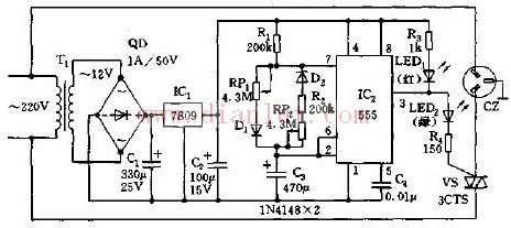
The cyclic timing socket consists of a buck rectifier circuit, a multi-vibrator with adjustable duty cycle, and a thyristor control circuit, as shown in the figure.
The step-down rectifier circuit consists of a step-down transformer T1, a full-bridge rectifier QD and a filter capacitor Cl. The rectified +15V voltage is regulated by a three-terminal regulator and outputs a stable voltage of +9V, which is used as a power supply for IC2.
IC2 (555) and R1, R2, RPl, RP2, C3, etc. form a multi-vibrator with adjustable duty cycle. Due to the connection of D1 and D2, the charging and discharging circuits are separated, and the connection of RP1 and RP2 can adjust the charging and discharging time of C3 separately, that is, the high power and low level duration of 555 can be adjusted separately. The charge and discharge time of 555 is
Tcharge=0.693(Rl+RPl)C2
t 放=0.693(R2+RP2)C3
The charge and discharge times of the illustrated parameters are all 1-25 minutes (calculated values ​​are 58.6 seconds - 1465 seconds).
The oscillation pulse of 555 output, during high electric drying, LED2 (green) lights up, thyristor VS is triggered to conduct, three-core socket CZ is energized, and the electric appliance on it is powered; during low level, LED1 Lights up in red (red), indicating power off and stop running. Therefore, adjusting RP1 can change the power-on time of the socket; adjusting RP2 can change the interval of power-off.
The 555 in the figure is the search and resonance mode, so the power-on and power-off of the socket is carried out by the search cycle mode, and the cycle period is T=tcharge+t==0.693 (R1+R2+RPl+RP2)C3 .
The cycle timing of this circuit is 2-50 minutes. The timing and period of the cycle can be adjusted according to actual needs. In terms of component selection, transformer T1 can use 220V/12V, 5VA AC step-down transformer; thyristor can use two-way thyristor with withstand voltage above 400V, its capacity depends on the load of the socket and load, such as 3CTSlA , 3CTS3A, 3CT5A, etc. Potentiometers RPl, RP2 can be selected with line type WH5 solid potentiometer, with adjustment knob.
General Purpose Frequency Inverter
General Purpose Frequency Inverter,Three Phase Variable Frequency Converter,Triple Phase Frequency Converter,Single Phase Frequency Inverter
Zhejiang Kaimin Electric Co., Ltd. , https://www.ckmineinverter.com