The circuit of the step-up switching regulator consisting of 555 timer is shown in the figure.
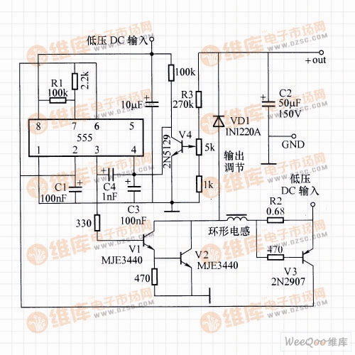
Step-up switching regulator circuit composed of 555 timer
Circuit working principle: It can be seen from the figure that during operation, C1 alternately charges and discharges, and resistor R1 sets the lowest switching frequency. When C1 is charged, the Darlington tube V1 to V2 are driven via the third leg of the 555 timer to supply the inductor current. When the inductor current reaches the turn-on voltage determined by the be poles of R2 and V3, the collector current of V3 accelerates the charging of C1.
When the voltage across C1 reaches the 555 reset point, the potential of the third pin becomes low, and V1 to V2 are turned off, and C1 starts to discharge through the second leg of 555. In the off condition, the back electromotive force of the inductor causes the collector voltage of V1 to V2 to rise, and the diode VD1 introduces the current of the inductor into the capacitor C2. When the discharge voltage of C1 reaches the set threshold, the third leg of 555 becomes high again, and so on.
The regulation of the output voltage is achieved by monitoring the voltage across C2. Whenever V4 is turned on (the output voltage is increasing), its collector will pull the reset pin potential of 555 low, thus driving the drive from V1 to V2 until the output voltage drops slightly. A low pass filter consisting of C3 helps keep the circuit stable during regulation.
The circuit in the figure can be upgraded from 7.5V input power supply to 80V/1OmA output power supply with an efficiency of at least 60%. The toroidal inductance value is a few hundred microhenries. Change R3 to coarsely adjust the regulation value.
Capacitor Motor,Furnace Capacitor,Start Capacitor,Capacitor Start Motor
Wentelon Micro-Motor Co.,Ltd. , https://www.wentelon.com