In the design, the reversing radar uses the PIC18F258 single-chip microcomputer as the control core to control the ultrasonic transmitting and receiving circuit and the temperature correction circuit. The PIC18F258 microcontroller itself has a CAN bus, which reduces the complexity of the circuit. The ultrasonic transmitting circuit emits ultrasonic waves of 40 kHz. After the obstacle is reflected, the probe receives the reflected wave. The single chip calculates the distance between the obstacle and the vehicle according to the difference between the transmitting and receiving time, and sends the message to the meter unit through the CAN bus and displays it. It can also be sent to the audio unit for voice alarm. When the distance is less than a certain value, the corresponding brake unit will automatically brake. The temperature compensation circuit uses the digital temperature sensor DS18B20 to correct the sound speed by the relationship between the speed of sound and the temperature, thereby eliminating the influence of temperature changes on the sound.
Reversing radar unit interface circuit design
The hardware configuration of the CAN unit generally has two forms. One form is a microcontroller with an internal integrated CAN controller plus a transceiver; another form is a general purpose microcontroller plus a separate CAN controller plus a transceiver. This design adopts the former form and does not occupy the port resources of the microcontroller, which simplifies the design of the interface circuit. Considering that the car works in a very special environment, Mierochip's PIC18F258 MCU, which meets the temperature range of the car and is cost-effective, has been selected. The chip integrates a CAN controller, which simplifies the hardware design of the system and improves the system. reliability. The reversing radar unit and CAN bus interface hardware circuit shown in Figure 3, mainly consists of PIC18F258 microcontroller, 6N137 high-speed optocoupler, PCA82 C250 bus transceiver three parts.
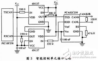
In order to improve the system's anti-interference ability and ability to transmit signals, the 6N137 high-speed optocoupler circuit can achieve good electrical isolation between the units on the bus. The two power supplies Vcc and V'cc of the high speed optocoupler must be completely isolated using a power isolation circuit.
2.0mm Wire To Board Connectors
Overview of 2.0mm Pitch Wire To Board Connectors
The 2.0 mm PH connector is a low- profile and compact component delivering dependable service in requirements for high density connection to printed circuit boards.
Designed harsh environments which are frequently subjected to heat and vibration such as in heavy equipment vehicles and batteries
Delivers up to a current rating of 2.0 A and 250 V, applicable for American Wire Gauge (AWG) #24, #25, #26, #27, #28, #30, #31, #32.
Enclosing this connector is a crimp style lock designed by Antenk and a special configuration which prevents users from inverted insertion.
General Specifaction 2.0mm Wire To Board Connectors
Contact Pitch 2.0mm
No.of Contacts 2 to 16 positions
Current 2A (AWG #22 to #28)
Compatible Cross Jst PH Connector Series
Current Rating: 2A
Voltage Rating: 250V
Temperature Range: -25°C~+85°C
Contact Resistance: 20m Omega Max
Insulation Resistance: 1000M Omega Min
Withstanding Voltage: 800V AC/minute
Advantages 2.0mm Wire To Board Connectors
2.0 mm pitch serves as the best choice for densely crowded electronics systems for its small, square-edged configuration, ruggedized and shock resistant feature.
Caters Power, Signal and Grounding Contact Needs
This connector can either stand as power contacts, signal contacts or both as power and signal contacts or a signal and grounding contact. The wiring harness interconnects the PCB to various components that sends signals and power to other electronic devices.
Safe and Reliable
2.0 mm pitch connectors ensures safety, system protection and performance with its bonded metallic conduits and multiple grounding points preventing fire hazards, component damage, overheating and possible electrocution.
ROHS Compliant
The product does not contain restricted chemicals in concentrations not complying with ROHS standards. Thus, for its components, the products can be worked upon at high temperatures required by lead-free soldering.
Features and Benefits of 2.0mm Pitch Wire To Board Connectors
Smallest pitch for positive lock Wire-to-Board crimp system
Provides space savings for mounting other components
mating retention with low mating and unmating forces
Wide header variations to provides customers with many choices and design flexibility
Easy to mate and unmate
Space saving SMT Mounting that provides assembly and cost efficiencies
Automated assembly reduces manual labor processes
Application industry of 2.0mm Pitch Wire To Board Connectors:
Automotive
Electronic modules
Consumer
Air conditioner Mobile POS terminals Notebook PCS mart meters TVs Televisions UAVs/Drones
Industrial
Servo motor
Medical
Patient Monitor
This is not a definitive list of applications for this product. It represents some of the more common uses.
Led Connector,2.0Mm Wire To Board Connectors,2.0Mm Pcb Wire To Board Connector,2.0Mm Pin Wire To Board Connector
ShenZhen Antenk Electronics Co,Ltd , https://www.coincellholder.com