0 Preface
Thanks to the rapid development of electronic technology, there are many MCUs and driver chips. Stepper motor drivers manufactured by many domestic manufacturers perform very well, but the basic requirements for drivers are the same: high cost performance, simple control, and safety and reliability. The author designed a constant current chopping two-phase stepper driver based on L298+L297. The driver itself has a pulse signal source to facilitate the user to perform some simple control, setting and use. In the whole, half-step control, can maintain constant torque output, superior performance than similar products on the market. The driver chopping current is larger, constant torque output, reliable operation, built-in pulse signal source to facilitate the user to do some simple control, set and use very convenient.
1 L297 Functional Analysis
L297 chip uses analog/digital circuit compatible I2L technology, 20-pin DIP package, usually 5 V power supply, all signals TTL/CMOS compatible, is a special chip that is very suitable for two-phase stepper motor control. L297 internal logic block diagram shown in Figure 1, the core circuit is the converter.
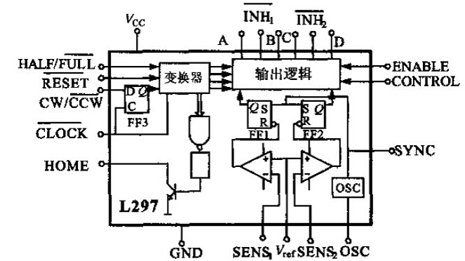
Figure 1 L297 internal logic diagram
Four output signals are generated by the converter to the subsequent output logic section. The output logic provides the phase sequence required for the disable and chopper functions. In order to obtain good speed and torque characteristics of the motor, the phase sequence signal is controlled by two PWM choppers. The chopper contains a comparator, a flip-flop, and an external sense resistor. Figure 2 shows the internal oscillation of the chip. The device provides a chopping frequency pulse. The oscillation frequency f of the oscillator output is determined by the external RC of the OSC and the frequency is 1/0.69RC. Each flip-flop's flip-flop is pulsed by the oscillator. The voltage across the sense resistor increases as the load current increases. When the voltage reaches Vref (Vref is based on the peak load current), the flip-flop is reset. The output is cut off until the second oscillation pulse arrives. The output of this line (ie, the flip-flop Q output) is a constant-rate PWM signal. The input of the CONTROL terminal of L297 determines the chopper-to-phase line A, B, C, D. Or inhibition lines INH1 and INH2 function. When CONTROL is high, it inhibits A, B, C, and D; when it is low, it inhibits INH1 and INH2, so that the motor torque can be controlled.

Figure 2 External detection resistor
2 L298 functional analysis
The L298 chip is a high voltage, high current dual H-bridge power IC that can be used to drive inductive loads such as relays, coils, DC motors, and stepper motors. It has two inhibit inputs to make the device immune to the input signal. The emitters of the triodes of each bridge are connected together, and the corresponding external terminals can be used to connect peripheral feedback resistors. Another input supply can be placed so that logic can operate at low voltage. L298 internal logic block diagram shown in Figure 3.

Figure 3 L298 internal logic diagram
L298 logic truth table shown in Figure 4, when EnA is low, IN1, IN2 input level is suppressed, the bridge is disconnected, the motor stops. When EnA is high, the IN1, IN2 input levels are high and low, the motor is positive or negative; IN1, IN2 are both low or high, the bridge is disconnected, and the motor stops.
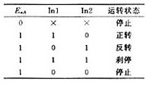
Figure 4 Logical truth table for L298
3 stepper motor drive characteristics
Two-phase stepper motor coil winding is divided into +A/-A phase and +B/-B phase, ignoring the non-linear factors between the electromagnetic torque and current, to make the motor smooth and constant torque, the key is to control The current in the motor windings is shown in Figure 5.
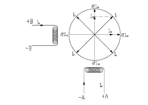
Figure 5 Current in the motor winding
In the basic step single-phase excitation driving mode, the phase winding current will be cycled according to I+A→I+B→IA→IB 4; in the basic step two-phase excitation driving mode, the phase winding current will be I+A, I + B → I + B, IA → IA, IB → IB, I + A 4 beat cycle, that is, the current vector of the full-step drive mode divides a circle into four equal parts; in a single step, two-phase alternate excitation Drive mode, the phase winding current will be according to, I + A → I + A, I + B → I + B → I + B, IA → IA → IA, IB → IB → IB, I + A 8 shot cycle, That is, a half-step current vector can divide a circle into 8 parts. The stepping current generated in the two-phase excitation mode will be the combined current vector of each phase, namely, I1, I2, I3, I4, and the amplitude thereof is a multiple of the single-phase current value. Therefore, in the half-step single-phase and two-phase excitation drive mode, in order to maintain a constant torque, when the current is converted from two-phase to single-phase, such as IB, I+A→I+A, the current of the +AA phase winding must be increased. To the double-phase current I + A times, the half-step torque operating current changes with time as shown in Figure 6.
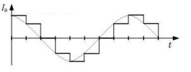
Similarly, when the basic step two-phase excitation driving mode is changed to the basic step single phase excitation driving mode, the output torque must be maintained constant, and the phase current must also be double the current of the two phases. Because the step resolution of the half-step single-phase and two-phase excitation methods is doubled and the motor operation is more stable, the phase coil of the basic step two-phase excitation method has a high utilization rate and can generate a large torque, and at the same time, Electromagnetic damping, weakening or eliminating the oscillation phenomenon, these two control methods are used more often.
Due to the influence of the winding inductance, the current in the winding will rise regularly. Therefore, in order to obtain good high-frequency performance, the current rise waveform in the winding becomes steeper, and a high voltage driving method can be used to shorten the time for the current to rise to the reference current I, to obtain a better pull-out torque and to improve the motor start-up. performance.
4 circuit solutions
The stepper motor control drive circuit of this design includes a power circuit, a control drive circuit, and an overcurrent detection circuit.
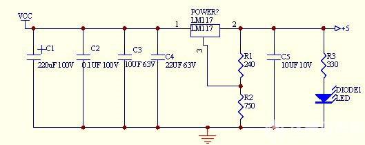
Power circuit, as shown in Figure 7. The internal 5V power is taken from the LM117. The LM117 incorporates multiple protection circuits such as overload protection and safe area protection. The allowable power supply voltage is +24 to +40V. The C1, C2, and C3 connected to the front end of the LM117 are used to cancel the inductance effect at the input terminal. Generate self-induced effects. C5 is designed not to cause large fluctuations in the output voltage when the load current is increased or decreased instantaneously. The LED is the power indicator.
Control drive circuit and overcurrent detection circuit, as shown in Figure 8.
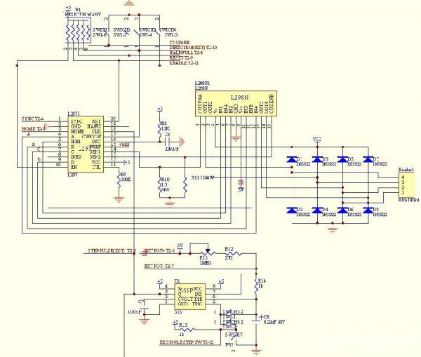
Figure 8 Control Drive and Overcurrent Detection Circuit
The basic function of the two-phase constant-current carrier stepper driver is the direction of the motor, and the speed can be controlled by the pulse signal sent by the upper computer. In consideration of the safe operation of the device, it should have an emergency stop (enable) function. The LLOCK CLOCK can be received from the host computer. The rising edge of each CLOCK causes the internal converter to change state, generate control sequences, and output from pins a, b, c, and d. L297 also has an internal synchronous ripple output function to facilitate synchronization of multiple drivers; internal half
Step/full step control etc. For a single device, such a drive may be sufficient, and when it comes to a variety of customers, different devices, the need for the motor is not the same, the natural current is not the same size, then in the design of the drive, you also need from this From the economical point of view, the driver should have the function of adjusting the current size. As shown in Fig. 9 , when sliding the varistor R7, the collector potential of the NPN tube becomes smaller. When the NPN tube acting as a switch is fully turned on, the potential of the emitter is approximately equal to the collector potential, that is, the Vref at L297 becomes smaller, and the L298 feedback resistor is The highest potential is Vref. At this time, from the formula Vref=I*r (feedback resistance), it can be seen that the I in the winding will also become smaller and vice versa. The feedback resistance in this circuit is R10, R11, and the value is 1.0Ω/4W. So the motor current I(A) = Vref/1.0Ω. Only the multimeter can measure the voltage across the 1 and 2 of JT2 to get the corresponding current I.
Although the L297+L298 driver has internal half-step/full-step control, if the control circuit is not improved, the peak current of the output will not change, which will cause the output torque of the double-phase full-step to be twice that of the single-phase step. There is also such a problem in the half-step state. The unsteady torque output will cause the drive's application range and reliability to be compromised.
Therefore, in order to ensure constant torque commutation of the stepper motor, the author has shown in Fig. 9 that
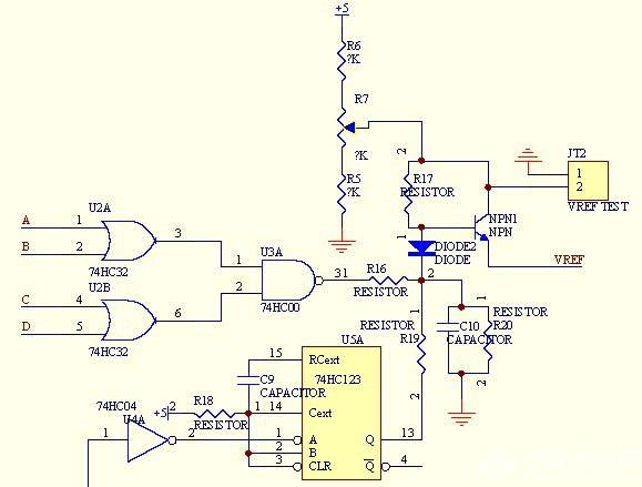
Figure 9 Constant Torque Commutation Control
The L297 output timing signal a, b, c, d signal through the OR gate 7432 phase or after the NAND gate 7400 and after, set R16 low or high, thereby changing the NPN tube base potential, control The Vref voltage input to L297. When L297 outputs a single-phase excitation signal or a half-step single-phase excitation signal to make the phase winding work in a single phase, it will increase the Vref voltage by a factor of two. Considering the nonlinearity of the torque current characteristics, the selected component parameters can be increased approximately 1.4 times. On the other hand, in order to increase the phase winding current rise time at the initial time of the step pulse, the Vref level needs to be increased. I invert the clock input 74123 one-shot A, at the same time when the L297 converter changes state, 74123 in its Q-side output time constant is 0.45 * R18 * C9 high, so that through R19 to control NPN The tube increases the Vref of L297 during this time.
In practical applications, the equipment needs debugging, diagnosis, etc. The internal 555 oscillator of the driver is shown in Figure 8. By adjusting the sliding rheostat R15, the Q output pulse frequency of the oscillator can be changed. The frequency variation range is 10HZ to 2000HZ, and the clock through L297 is used. Control the switching speed of the L298 bridge and increase the stepping speed of the motor. If you want to set a single step, you only need to open the switch SW-2. The L297's CW/CCW direction can also be controlled by the SW-4 switch's high and low levels. When an external pulse is required, only switch SW-6 turns off the internal pulse.
5 Test Study
Connect the SIZE17 two-phase hybrid stepper motor to the driver. The driver power supply voltage is 24VDC. Set the driver to work in the full-step two-phase excitation mode as shown in Figure 10, and the full-step single-phase excitation mode as shown in Figure 11, half-step single-phase and two-phase excitation modes. As shown in Figure 12. The current waveform of a phase winding measured with an oscilloscope and a current clamp:

Figure 10 Full-step two-phase excitation
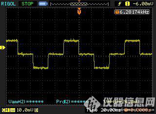
Figure 11 Single step excitation
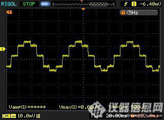
Figure 12 Half-step excitation
From the perspective of single-phase excitation and half-step excitation, the peak current in the single-phase state is higher than the peak value in the two-phase state. The actual test is about 1.3-1.5 times, which meets the design requirements.
6 Conclusion
The stepping motor driver is suitable for two-phase and four-phase bipolar stepping motors whose driving voltage does not exceed 40V and whose current does not exceed 2.0A, and basically covers mainstream hybrid stepping motors with SIZE23 or less. Widely used in medical equipment, analytical instruments, based on the main chip L297, L298 technology is mature, the price is cheap, this driver is cost-effective, the market sales, feedback is good.
references:
[1] ZHAO T. Applicatim of 3955 in steper motor microstep—ping control[J]. Mechanical& Electrical Engineering Magazine, 2003, 20(2):46-49.
[2] Shi Jingzhuo. Stepper motor servo control technology. Beijing: Science Press, 2006-7-1
[3] Deng Xingzhong. Electromechanical Drive Control. Huazhong University of Science and Technology Press. 1998
[4] Tan Jiancheng. Motor Control Application Specific Integrated Circuit [M]. Beijing: Mechanical Industry Press, 2003
Fiber Optic Distribution Box,Fiber Optic Breakout Box,Fibre Optic Breakout Box,Fibre Break Out Box
Cixi Dani Plastic Products Co.,Ltd , https://www.cxdnplastic.com