This application note uses the 6-axis sensor MPU6050 that drives the I2C interface as an example to illustrate how to develop an application using the I2C device driver interface, and explains in detail the RT-Thread I2C device driver framework and related functions.
1 Purpose and structure of this paper
1.1 Purpose and background of this article
The I2C (or i2c, IIC, iic) bus is a simple, bidirectional two-wire (clock SCL, data SDA) synchronous serial bus developed by Philips. It requires only two wires to transfer information between devices connected to the bus, making it one of the most widely used communication interfaces for semiconductor chips. The I2C device driver framework is introduced in RT-Thread. The I2C device driver framework provides two underlying hardware interfaces based on GPIO emulation and hardware controllers.
1.2 Structure of this paper
This paper first describes the basic situation of the RT-Thread I2C device driver framework, then describes the I2C device driver interface in detail, and writes the driver of the MPU6050 using the I2C device driver interface, and gives the verification on the punctual atom STM32F4 explorer development board. Code sample.
2 Introduction to I2C Device Driver Framework
When using MCU for project development, I2C bus is often used. In general, the MCU has an I2C controller (hardware I2C), and the same function can be implemented by simulating the I2C bus protocol using two GPIOs of the MCU.
RT-Thread provides an I/O device management framework that divides I/O devices into three layers: the application layer, the I/O device management layer, and the underlying driver. The I/O device management framework provides a unified device operation interface and an I2C device driver interface for the upper layer application, and provides the underlying driver interface for the lower layer. The application accesses the underlying device through the standard interface provided by the I/O device module. The change of the underlying device does not affect the upper-layer application. This way, the application is very portable, and the application can be easily accessed from a The MCU is ported to another MCU.
This article takes the 6-axis inertial sensor MPU6050 as an example, and uses the GPIO analog I2C controller provided by the RT-Thread I2C device driver framework to explain how the application uses the I2C device driver interface to access the I2C device.
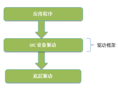
Figure 2-1 RT-Thread I2C device driver framework
3 Run the I2C device driver sample code
3.1 Sample Code Software and Hardware Platform
Punctual atom STM32F4 explorer development board
GY-521 MPU-6050 module
MDK5
RT-Thread source
The MCU of the punctual atom explorer STM32F4 development board is STM32F407ZGT6. This example uses USB serial port (USART1) to send data and power, and SEGGER JLINK to connect JTAG debugging.
The GY521 module used in this experiment is a 6-axis inertial sensor module with an onboard MPU6050. We use PD6 (SCL) and PD7 (SDA) of the development board as analog I2C pins, connect the SCL hardware of the GY521 module to PD6, connect SDA to PD7, connect GND to the GND of the development board, and connect VCC to 3.3. V.
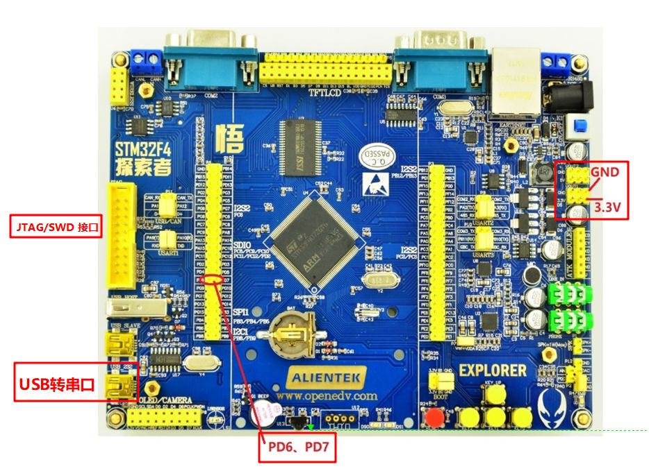
Figure 3.1-1 Punctual atom development board
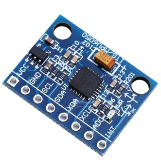
Figure 3.1-2 GY521 module
Based on the punctual atom STM32F4 explorer development board, this paper gives the method of adding the underlying I2C driver (GPIO analog mode) and the specific application code of the I2C device (taking the MPU6050 as an example), including register read and write operations. Due to the versatility of the upper-level application API of RT-Thread, the code is not limited to a specific hardware platform, and users can easily port it to other platforms.
3.2 Enabling I2C Device Drivers
Use the env tool command line to enter the rt-thread\bsp\stm32f4xx-HAL directory, then enter the menuconfig command to enter the configuration interface.
Configure the shell to use the serial port 1: Select Using UART1, enter the RT-Thread Kernel ---> Kernel Device Object menu, and modify the device name for console to be uart1.
Go to the RT-Thread Components ---> Device Drivers menu and select Using I2C device drivers. This example uses GPIO to simulate I2C, so use Use GPIO to simulate I2C.

Figure 3.2-1 Opening i2c with menuconfig
Exit the menuconfig configuration interface and save the configuration. Enter the scons --target=mdk5 -s command on the env command line to generate the mdk5 project. The new project is named project. Open the project with MDK5, modify the MCU model to STM32F407ZGTx, and modify the debugging option to J-LINK.

Figure 3.2-2 Modifying the MCU
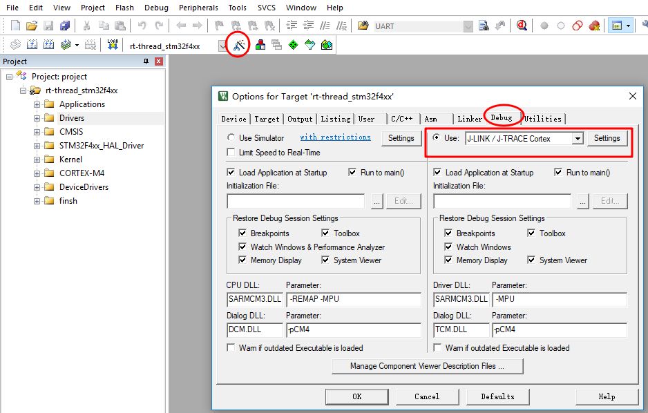
Figure 3.2-3 Modifying debug options
2. After compiling the project, download the program to the development board to run. On the terminal PuTTY (open the corresponding port, the baud rate is set to 115200), enter the list_device command to see the device named i2c2. The device type is I2C Bus, indicating that the I2C device driver is successfully added. as the picture shows:
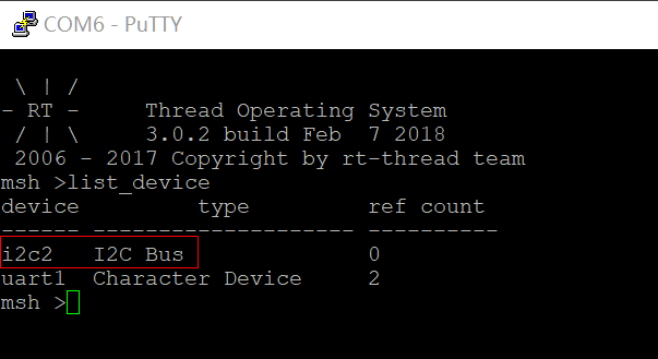
Figure 3.2-4 Viewing the i2c Bus Using the list_device Command
3.3 Running the sample code
Copy main.c from the I2C sample code (please reply to AN0003, download the sample code) to the t-thread\bsp\stm32f4xx-HAL\applications directory and replace the original main.c. Drv_mpu6050.c, drv_mpu6050.h are copied to the t-thread\bsp\stm32f4xx-HAL\drivers directory and added to the corresponding group in the project. as the picture shows:
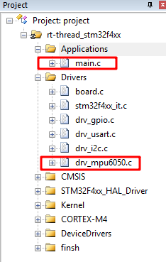
Figure 3.3-1 Adding a driver
In this example, GPIO PD6 is used as SCL and GPIO PD7 is used as SDA. The I2C bus name is i2c2. The reader can modify the following parameters in drv_i2c.c as needed to adapt to its own board, and ensure the macros MPU6050_I2C_BUS_NAME and drv_i2c defined in drv_mpu6050.c The macro I2C_BUS_NAME in .c is the same. This example needs to change the drv_i2c.c default driver port GPIOB to GPIOD, as shown in the following figure:

Figure 3.3-2 i2c board level configuration in drv_i2c.c
Connect the MPU6050 module and development board, compile the project and download the program to the development board, reset the MCU, the terminal PuTTY will print out the read MPU6050 sensor data, which is temperature, triaxial acceleration, triaxial angular velocity:

Figure 3.3-3 Terminal printing information
4 I2C device driver interface detailed
According to the previous steps, I believe that readers can quickly run the RT-Thread I2C device driver. How to use the I2C device driver interface to develop applications?
The RT-Thread I2C device driver currently only supports the host mode. To use the RT-Thread I2C device driver, you need to use the menuconfig tool to enable the macros RT_USING_DEVICE and RT_USING_I2C. If you want to use GPIO to simulate I2C, you need to enable the macro RT_USING_I2C_BITOPS.
The general flow of using an I2C device driver is as follows:
You can use the list_device command in the msh shell to view existing I2C devices and determine the I2C device name.
The lookup device uses rt_i2c_bus_device_find() or rt_device_find() to pass in the I2C device name to get the i2c bus device handle.
Use rt_i2c_transfer() to send data and receive data. If the host only sends data, you can use rt_i2c_master_send(). If the host only receives data, you can use rt_i2c_master_recv().
Next, this chapter will explain the use of the I2C device driver interface in detail.
4.1 Finding devices
To use an I2C device that has been managed by the operating system, the application needs to call the lookup device function to find the I2C device before it can transfer information to the device.
Prototype: struct rt_i2c_bus_device *rt_i2c_bus_device_find(const char *bus_name)
| Bus_name | I2C device name |
Function return: I2C device handle is returned if the I2C device exists, otherwise RT_NULL is returned.
This article sample code under the driver drv_mpu6050.c mpu6050_hw_init () find the device source code as follows:
#define MPU6050_I2CBUS_NAME "i2c2" /* I2C device name must be the same as the I2C device name registered with drv_i2c.c */ static struct rt_i2c_bus_device *mpu6050_i2c_bus; /* I2C device handle */ ... ... ... int mpu6050_hw_init (void) {rt_uint8_t res; mpu6050_i2c_bus = rt_i2c_bus_device_find (MPU6050_I2CBUS_NAME); / * find I2C device * / if (mpu6050_i2c_bus == RT_NULL) {MPUDEBUG ( "can not find mpu6050% s device", MPU6050_I2CBUS_NAME); return -RT_ERROR ; } ... ... ... ... }
4.2 Data transmission
The core API of the RT-Thread I2C device driver is rt_i2c_transfer(), which delivers messages in a chained structure. Through the message chain, the call can be used to send and receive multiple times of data. This function can be used to send data or receive data.
Function prototype:
Rt_size_t rt_i2c_transfer(struct rt_i2c_bus_device *bus, struct rt_i2c_msg msgs[], rt_uint32_t num)
| Bus | I2C bus device handle |
| Msgs[] | I2C message array |
| Num | Number of message arrays |
Function returns: the number of successfully transmitted message arrays
The message array msgs[] is
Struct rt_i2c_msg { rt_uint16_t addr; // slave address rt_uint16_t flags; //flag, read, write, etc. rt_uint16_t len; //read and write data bytes rt_uint8_t *buf; //read and write data pointer}
The addr slave address supports 7-bit and 10-bit binary addresses (flags |= RT_I2C_ADDR_10BIT). The slave address used by the RT-Thread I2C device driver interface is an address that does not contain read/write bits. The read/write bits correspond to the modified flags.
The flags flag can be selected as the macro defined in the i2c.h file. The transmit data is assigned RT_I2C_WR, and the receive data is assigned RT_I2C_RD. It can be combined with other macros using the bit operation "|" as needed.
#define RT_I2C_WR 0x0000 #define RT_I2C_RD (1u << 0) #define RT_I2C_ADDR_10BIT (1u << 2) / * this is a ten bit chip address * / #define RT_I2C_NO_START (1u << 4) #define RT_I2C_IGNORE_NACK (1u << 5 #define RT_I2C_NO_READ_ACK (1u << 6) /* when I2C reading, we do not ACK */
4.2.1 Sending data
The user can call the I2C device driver interface rt_i2c_master_send() or rt_i2c_transfer() to send the data. The function call relationship is as follows:
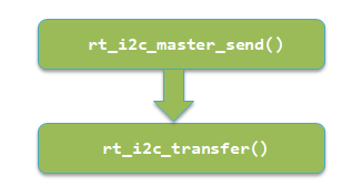
Figure 4.2.1-1 Send data function call relationship
The mpu6050_write_reg() function in drv_mpu6050.c is the MCU that writes data to the mpu6050 register. There are two implementations of this function, which are called by the I2C device driver interface rt_i2c_transfer() and rt_i2c_master_send() respectively.
The MPU6050 data sheet used in this example shows that the 7-bit slave address is 110100X, X is determined by the AD0 pin of the chip, and the AD0 of the GY521 module is connected to GND. Therefore, the address of the MPU6050 as a slave is 1101000, and the hexadecimal form is 0x68. Write a register of MPU6050, the host first sends the slave address MPU6050_ADDR, the read/write flag R/W is RT_I2C_WR (0 is write, 1 is read), then the master sends the slave register address reg and data data.
Send data using rt_i2c_transfer()
The sample code underlying driver drv_mpu6050.c in this article sends the data source as follows:
#define MPU6050_ADDR 0X68 //Write mpu6050 single register //reg: register address //data: data // return value: 0, normal / -1, error code rt_err_t mpu6050_write_reg(rt_uint8_t reg, rt_uint8_t data) { struct rt_i2c_msg msgs; rt_uint8_t Buf[2] = {reg, data}; msgs.addr = MPU6050_ADDR; /* slave address */ msgs.flags = RT_I2C_WR; /* write flag */ msgs.buf = buf; /* send data pointer */ msgs .len = 2; if (rt_i2c_transfer(mpu6050_i2c_bus, &msgs, 1) == 1) { return RT_EOK; } else { return -RT_ERROR; } }
For example, in this example code, rt_i2c_transfer() is used to send data. The slave MPU6050 address hexadecimal value is 0X68, the register address reg hexadecimal value is 0X6B, and the transmitted data hexadecimal value is 0X80. The sample waveform is shown in the figure below. The first data sent is 0XD0. The upper 7 bits of the first data are the slave address, and the lowest bit is the read/write bit is write (the value is 0), so the first data is: 0X68 << 1|0 = 0XD0, then send register address 0X6B and data 0X80 in sequence.

Figure 4.2.1-2 Example of I2C Transmit Data Waveform
Send data using rt_i2c_master_send()
Function prototype:
Rt_size_t rt_i2c_master_send(struct rt_i2c_bus_device *bus, rt_uint16_t addr, rt_uint16_t flags, const rt_uint8_t *buf, rt_uint32_t count)
| Bus | I2C bus device handle |
| Addr | Slave address, does not contain read/write bits |
| Flags | Flag, read and write flags are written. Only supports 10-bit address selection RT_I2C_ADDR_10BIT |
| Buf | Pointer to send data |
| Count | Number of bytes sent |
Function Returns: The number of bytes of data successfully sent.
This is a simple wrapper around rt_i2c_transfer().
The sample code underlying driver drv_mpu6050.c in this article sends the data source as follows:
#define MPU6050_ADDR 0X68 //Write mpu6050 single register // reg: register address //data: data // return value: 0, normal / -1, error code rt_err_t mpu6050_write_reg(rt_uint8_t reg, rt_uint8_t data) { rt_uint8_t buf[2] ; buf [0] = reg; buf [1] = data; if (rt_i2c_master_send (mpu6050_i2c_bus, MPU6050_ADDR, 0, buf, 2) == 2) {return RT_EOK;} else {return -RT_ERROR;}}
4.2.2 Receiving data
The user can call the I2C device driver interface rt_i2c_master_recv() or rt_i2c_transfer() to accept the data. The function call relationship is as follows:

Figure 4.2.2-1 Receive data function call relationship
The mpu6050_read_reg() function in the sample code drv_mpu6050.c is the MCU reading data from the MPU6050 register. There are also two ways to implement this function, which are called by the I2C device driver interface rt_i2c_transfer() and rt_i2c_master_recv().
Read a register of MPU6050, the host first sends the slave address MPU6050_ADDR, the read/write flag R/W is RT_I2C_WR (0 is write, 1 is read), and the slave register address reg can start reading the device. Then send the slave address MPU6050_ADDR, the read/write flag R/W to RT_I2C_RD (0 is write, 1 is read), and the read data pointer is saved.
Receive data using rt_i2c_transfer()
The sample code underlying driver drv_mpu6050.c in this article receives the data source as follows:
#define MPU6050_ADDR 0X68 //Read register data //reg: register address to be read //len: number of data bytes to read //buf: read data storage area // return value: 0, Normal / -1, error code rt_err_t mpu6050_read_reg(rt_uint8_t reg, rt_uint8_t len, rt_uint8_t *buf) { struct rt_i2c_msg msgs[2]; msgs[0].addr = MPU6050_ADDR; /* Slave Address*/ msgs[0].flags = RT_I2C_WR; /* Write flag */ msgs[0].buf = ® /* Slave register address */ msgs[0].len = 1; /* Send data bytes */ msgs[1].addr = MPU6050_ADDR; /* Slave Address*/ msgs[1].flags = RT_I2C_RD; /* Read Flag*/ msgs[1].buf = buf; /* Read Data Pointer*/ msgs[1].len = len; /* Read data bytes */ if (rt_i2c_transfer(mpu6050_i2c_bus, msgs, 2) == 2) { return RT_EOK; } else { return -RT_ERROR; } }
For example, in this example code, when rt_i2c_transfer() is called to receive data, the slave MPU6050 address hexadecimal value is 0X68, and the register address reg hexadecimal value is 0X75. The sample waveform is shown in the figure below. The first data sent is 0XD0. The upper 7 bits of the first data are the slave address, and the lowest bit is the read/write bit is a write (value is 0), so the first data value is :0X68 << 1|0 = 0XD0, then send register address 0X75. The first data sent the second time is 0XD1, the read/write bit is read (value is 1), the value is: 0X68 << 1 | 1 = 0XD1, and then the received data 0X68 is received.
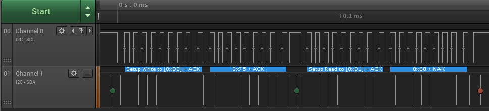
Figure 4.2.2-2 Example of I2C Transmit Data Waveform
Receive data using rt_i2c_master_recv()
Function prototype:
Rt_size_t rt_i2c_master_recv(struct rt_i2c_bus_device *bus, rt_uint16_t addr, rt_uint16_t flags, rt_uint8_t *buf, rt_uint32_t count)
| Bus | I2C bus device handle |
| Addr | Slave address, does not contain read/write bits |
| Flags | Flag, read/write flag is read, only supports 10-bit address selection RT_I2C_ADDR_10BIT |
| Buf | Accept data pointer |
| Count | Receive data bytes |
Function Returns: The number of bytes of data successfully received.
This function is a simple wrapper around rt_i2c_transfer() that can only read data (receive data).
The sample code underlying driver drv_mpu6050.c in this article receives the data source as follows:
#define MPU6050_ADDR 0X68 //Read register data //reg: register address to be read //len: number of data bytes to read //buf: read data storage area // return value: 0, normal / -1, the error code rt_err_t mpu6050_read_reg (rt_uint8_t reg, rt_uint8_t len, rt_uint8_t * buf) {if (rt_i2c_master_send (mpu6050_i2c_bus, MPU6050_ADDR, 0, ®, 1) == 1) {if (rt_i2c_master_recv (mpu6050_i2c_bus, MPU6050_ADDR, 0, buf, len) == len) {return RT_EOK;} else {return -RT_ERROR;}} else {return -RT_ERROR;}}
4.3 I2C device driver application
Generally, the read-only registers of the I2C interface chip are divided into two cases, one is a single function register, and the other is a register with consecutive addresses and similar functions. For example, the registers 0X3B, 0X3C, 0X3D, 0X3E, 0X3F, and 0X40 of the MPU6050 sequentially store the upper 8 bits and the lower 8 bits of the three-axis acceleration X, Y, and Z axes.
The sample code underlying driver drv_mpu6050.c uses the mpu6050_read_reg() function to read the 3-axis acceleration data of the MPU6050:
#define MPU_ACCEL_XOUTH_REG 0X3B //Acceleration value, X-axis high 8-bit register //Get acceleration value (original value) //gx,gy,gz: raw reading of gyroscope x,y,z axis (signed) //return value: 0, the success / -1, the error code rt_err_t mpu6050_accelerometer_get (rt_int16_t * ax, rt_int16_t * ay, rt_int16_t * az) {rt_uint8_t buf [6], ret; ret = mpu6050_read_reg (MPU_ACCEL_XOUTH_REG, 6, buf); if (ret = = 0) { *ax = ((rt_uint16_t)buf[0] << 8) | buf[1]; *ay = ((rt_uint16_t)buf[2] << 8) | buf[3]; *az = ( (rt_uint16_t)buf[4] << 8) | buf[5]; return RT_EOK; } else { return -RT_ERROR; } }
5 Reference
All relevant APIs in this article
| Rt_i2c_transfer() | Rt-thread\components\drivers\include\drivers\i2c.h |
| Rt_i2c_master_send() | Rt-thread\components\drivers\include\drivers\i2c.h |
| Rt_i2c_master_recv() | Rt-thread\components\drivers\include\drivers\i2c.h |
| Mpu6050_hw_init() | Drv_mpu6050.h |
| Mpu6050_write_reg() | Drv_mpu6050.h |
| Mpu6050_read_reg() | Drv_mpu6050.h |
| Mpu6050 _temperature_get() | Drv_mpu6050.h |
| Mpu6050 _gyroscope_get() | Drv_mpu6050.h |
| Mpu6050 _accelerometer_get() | Drv_mpu6050.h |

AC Input : 100V to 240V, DC Output: 12 volt at 2 amp rating . Please refer to the ASIN :B0746GCGQ8 if u need 10 units.
Type : Regulated Switching Power Supply with 2.1mm x 5.5mm plug , center positiveManufactured with high quality material and built-in protection of over current, over voltage, short circuits .
COMPACT DESIGN and LOW CONSUMPTION makes it ideal for taking around and using at home.
12v wall charger,12v switching adapter,(12V/2A) Switching Mode Power Adapter Wall Charger,12V 2A Power Supply Adapter,12 Volt 2 Amp Power Adapter,12V 3A Power Supply Adapter,12v3a wall charger
Shenzhen Waweis Technology Co., Ltd. , https://www.waweispowerasdapter.com