Hi-Fi is an abbreviation for High-Fidelity in English, meaning high-fidelity, meaning authentic reproduction of sound source information, namely authenticity. It requires the audio equipment to reproduce and process the sound signal without distortion in the replay process, so as to restore the original appearance of the sound source, emphasizing authenticity and mostly used for enjoying music. The Hi-Fi amplifier is a signal amplifier designed to reproduce the true nature of music with high fidelity.
Hi-Fi amplifier defect1, lack of confidence in the AV amplifier playing a large signal source
This point can be seen from the product specification, the AV amplifier output power in the two-channel state than the output power in the four-channel state. However, some manufacturer's instructions are the same. At this time, you can use a large dynamic range of music for auditioning, which can obviously feel powerless. This is because the total power consumption of the AV power amplifier is large, and the power supply power reserve is not sufficient, and the Hi-Fi power amplifier appears to be calm.
2, AV power amplifier line affects sound quality
AV amplifier sets a variety of video, audio ports, access to multiple audio and video signal sources, resulting in multiple signal lines and miscellaneous, easily lead to mutual interference of the signal. In particular, the presence of distributed capacitance has the greatest impact on high-frequency audio and its harmonics, which results in attenuation or interference of the original rich high-frequency components of the high-quality signal source, making the listener less familiar with high-fidelity effects.
3, AV power amplifier screen will also interfere with sound quality
The AV amplifier focuses on convenient multi-function operation. The panel is equipped with a large-scale fluorescent display, which makes the operation intuitive and vivid. However, the fluorescent screen is heated with a low-voltage AC filament, and the character display is driven by the pulse signal, which will radiate much electromagnetic interference to the surroundings. Affect sound quality.
If you want to enjoy movies and TV shows, then there is no doubt that you choose AV amplifiers. If you have a soft spot for music, then you still have to choose Hi-Fi amplifiers.
Hi-Fi amplifier input signal line connectionThe input part of the Hi-Fi amplifier (taking a amp as an example) refers to a signal transmission line from the input RCA socket to the volume potentiometer to the gate of the input stage voltage amplification tube (see Figure 1). It is generally connected with coaxial signal lines (shielded wires), and is often used in fever-class varieties, even silver wires. But usually only concerned with the two sections of the volume potentiometer in and out, as shown in Figure 1 AB, CD two-segment line. The input RL line from the negative terminal of the RCA socket to the ground, the GH line from the volume potentiometer ground to the ground, is usually an ordinary copper wire, or even a thin copper wire, and some distances between F and H. Very long, it may also be connected through a metal chassis. Although this connection method works well for the amplifier and even sound effects, this connection is asymmetrical and unbalanced for the signal in and out paths (positive and negative half cycles of the signal). It will have a certain influence on the speed, rhythm, details, and positioning of music. If the signal loop is balanced and symmetrical, the playback effect will be greatly improved, especially the high frequency performance.
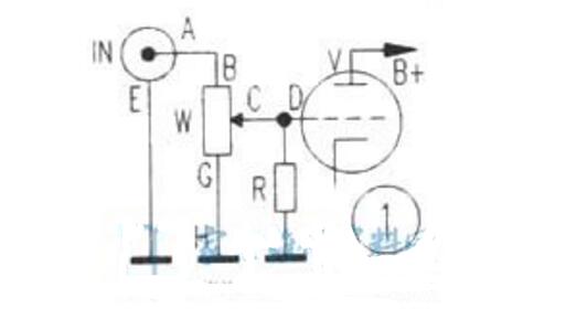
The reason is very simple. This is because the signal needs a smooth circuit during transmission. The wires of the positive and negative half cycles are different. The thickness is different and the length is different. The resistance and distributed capacitance are also different, the loss is not the same, and the sound performance is different. It will be affected, therefore, to make the amplifier have a more beautiful sound performance, it should be improved in the use of lines and connections.
The improvement method is very simple. As shown in Figure 2, connect the negative terminal of the RCA socket with the ground terminal of the volume potentiometer (the middle is no longer through the ground line), and the positive terminal and negative terminal are two lines to the volume potentiometer - - That is, A to B and E to G are equal, each using a same material, the same diameter, the same length of the coaxial signal line. Only one end of the shielding layer is grounded. If the segment CD is very short, you can use no shielded wire. However, the material of the wire and the diameter of the wire must be the same as those used by the segment AB, and the lengths of the two-channel segments are equal. The line is balanced and symmetrical.
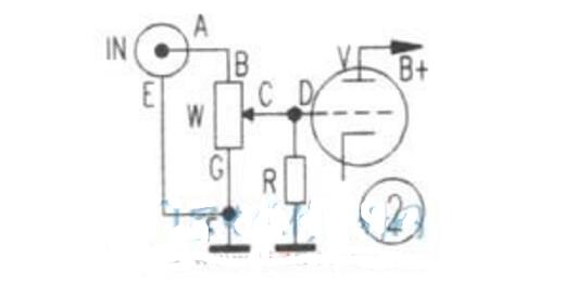
There are two-core and three-core varieties of bulk signal lines on the market. Each channel can be used with two cores, one core connected to A to B, one core connected to E to G, the shielding layer can be grounded. Three-core signal lines can also be used. One more core and the shielding layer are grounded together. One core must not be used for a single circuit. The two cores must be combined in a single circuit or each core must be used in a circuit. The other core should be empty. Grounding. It is better to use two-core or three-core small signal lines, because the two-core or three-core lines are gently twisted in the shielding layer, which can offset the magnetic lines of force, which is beneficial to the brightness of medium and high sound. If you use a single-core coaxial cable, you should twist the two loosely, but do not twist too tightly.
Symmetrical, balanced signal input circuit, can make music more perfect. If you are using a bile preamplifier or amplifier, input the ground connection of the RCA socket, volume potentiometer, etc., replace the wire with the same material, length, and wire diameter as the signal terminal. Different, more brilliant sounds.
25W Hybrid Hi-Fi Amplifier Circuit with Tone Control FunctionThe amplifier consists of an electronic tube for the preamplifier, audio-specific integrated circuits AD711 and LM1875 for the post-class, circuit distortion, low output impedance, large dynamic range, can guarantee a good sound quality.
1, the circuit worksThis circuit draws only the left channel portion, and the right channel is slightly omitted. The circuit uses a double-triode 6N2-type tube to form a line input amplifier (half of the 6N2 VE1L is used for the left channel and the other half is used for the right channel). R2 is the DC bias resistor of the input stage. When the current Iao flows through R2, a DC voltage Eg of about 1.5V is generated. The gate drain resistance R1 is applied to the gate of VE1L to form the negative gate voltage of the line amplifier. At this point VE1L works in Class A, with good linearity. Another function of R2 is to generate appropriate AC feedback on the source signal, which further reduces distortion and improves stability. The third role of R2 is to form pitch feedback. This input stage has several hundred kilohms of high input impedance, large dynamic range, good transient response and other outstanding advantages, which is exactly what Hi-Fi pre-class must do.
The attenuated tone control network (TCN) is inserted between the front and rear stages. The audio signal output from the VE2La cathode K on the SRPP circuit is fed to the pin 3 of the downstream integrated circuit IC1 via the volume potentiometer VR3; the other channel is fed to the cathode of the line amplifier VE1L via the TCN network. This combination can effectively suppress noise and distortion while maintaining the attenuating TCN regulation characteristics.
After being amplified by VE1L, the signal is output from the anode and is coupled through capacitor C2 to a power amplifier exciter VE2 composed of an electronic tube 6N3 with excellent high-frequency characteristics. The internal two triodes are connected in parallel to adjust the push-pull circuit SRPP. This circuit is characterized by small distortion, low output impedance, and large dynamic range. It is fully adaptable to various types of power amplifiers composed of ICs, FETs, TRs, and VALs.
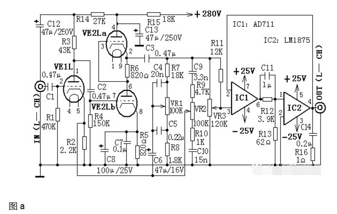
In Figure (a), capacitors C4, C5, resistors R7, R8, and potentiometer VR1 form a low tone control network. When VR1 is adjusted up, the network composed of C5 and C4 will increase the negative feedback amount of the low audio signal and the bass will be relatively weakened; otherwise, the bass will be relatively enhanced when the VR1 is lowered.
Capacitors C9, C10, resistors R9, R10 and potentiometer VR2 form a high tone control network. When VR2 is adjusted up, the amount of negative feedback of the high audio signal increases and the treble is relatively weakened; otherwise, the treble will be relatively enhanced when VR2 is adjusted downward.
In power amplifier circuits, it is desirable to obtain high fidelity and high power output. It is not difficult for general power amplifiers to provide large power for loads, but most of them have the disadvantages of large distortion and poor linearity. If you insert a linear op amp IC1 with good linearity and distortion at the front end of a high-power IC, and the IC2 of the amplifier is in the feedback loop of IC1, you can achieve the effect of avoiding weaknesses. This connection is called "turbocharged combination" (TCC). Integrated circuits IC1 (AD711) and IC2 (LM1875) constitute the rear stage of the TCC amplifier. In the TCC network, an RC network is formed by C11, R12, and R13 to provide appropriate phase compensation for the audio signal and stabilize the IC1 and IC2 frequency response areas.
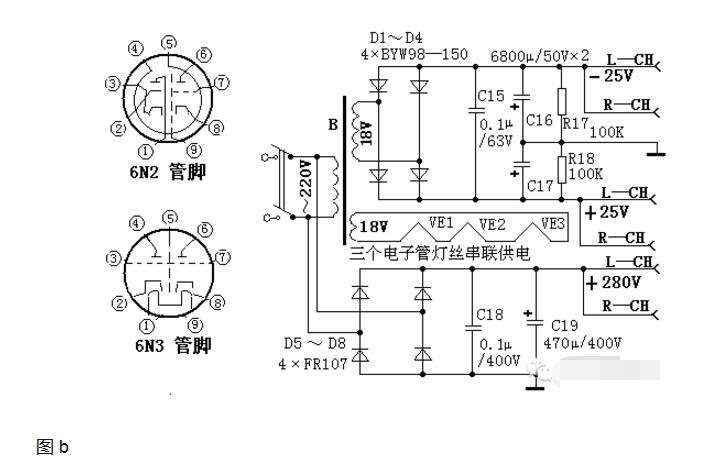
Figure (b) shows the overall power supply circuit diagram. The high voltage in the front stage of the electron tube is directly provided by the mains rectification to generate 280V DC power. The three filaments of the two electron tubes are connected in series, and a set of AC 18V power supply makes the circuit simple. The other set of AC 18V is bridge-rectified, C15, C16, C17, and the filter produces ±25V to supply IC1 and IC2.
2, the choice of componentsTube VE1 select 6N2, VE2 select 6N3, integrated circuit IC1 select AD711, IC2 select LM1875, low voltage filter capacitor C16, C17 select 70VW series, high voltage filter capacitor C19 select CD17H series, C15 select polyester capacitor, C18 select polypropylene capacitor, C6, C8 chooses tantalum electrolytic capacitors, and C12, C13 selects CD03HV high voltage electrolytic capacitors. All resistors use metal film series. Potentiometer used KK210 series. Component parameters are selected using the circuit icon note.
3, production and debugging methodsBy selecting the components and installing them as required, you can succeed at one time without debugging. The electronic tube should be installed with an electronic tube holder. The integrated circuit should be kept away from the electron tube as much as possible to avoid overheating of the integrated circuit. After the circuit is installed, it should be installed in a chassis with a cooling hole, and the volume potentiometer and the high and low pitch potentiometers are mounted on the chassis panel to facilitate adjustment.
Four HI-FI power amplifier circuit diagrams, 100W*2 HI-FI power amplifier circuitThe STK2100-2 is an enthusiast-grade high-power power amplifier integrated circuit. The output uses a power FET with the characteristics of an electron tube. The output power is 100W*2, the frequency response is 10HZ~20KHZ, and the circuit operating voltage is at least 12V positive and negative, and the highest is Positive and negative 50V, distortion is 0.01%. Using it to make a high-quality power amplifier, its peripheral circuit is very simple, distortion is small, the frequency band and output power and other parameters have reached the excellent indicators. Circuit shown in Figure 5-84, VD3 is a bridge bridge pickup circuit. When the power amplifier circuit is normal, RL only has AC signal, no DC voltage, and the pickup circuit does not work. VT1 cuts off, VT2, VT3 turns on, K pulls in, the amplifier output connects the Loudspeaker. When the circuit fails, VT1 is on, VT2, VT3 are off, K is released, and the Speaker is effectively protected. ICI is a fever-grade, low-noise, high-conversion-rate operational amplifier, the NE5535. The NE5535 output circuit is a PNP-NPN full symmetrical complementary structure with a certain quiescent current bias. The internal circuit is very simple. It has advantages such as open-loop frequency response, high unit gain bandwidth, high slew rate, small open-loop distortion, low noise, and good transient state characteristics. It can be used as a HiFi audio pre-amplifier circuit and is an ideal chip. For the operational barrier.
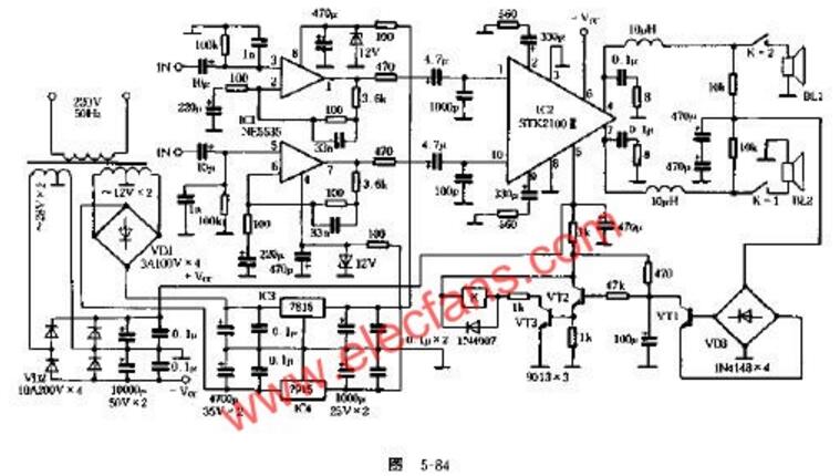
The circuit power transformer uses 250W ring type “Cigarâ€, the power amplifier is separated from the front power supply, plus high-quality electrolytic capacitors, so the reserve power is large enough. All resistors in the circuit are high quality metal film resistors. The capacitor uses germanium and CBB capacitors. Therefore, the whole commercial voice is very small, the midrange is bright, the bass is strong and thick, and it has a "bile" flavor.
2, low-pitched HI-FI amplifier circuitThe self-made power amplifier is TL082 and TDA1521, and the circuits are shown in Figure 5-74 and Figure 5-75. The machine power supply voltage is best not to be higher than the double 14V, but the power can not be lower than 20W, choose dual 12VE type transformer, all resistance is 1/4W5 ring gold film. Capacitor used domestic monolith, deep-lun. The input of TDA1521 adopts SANYO's 47pF/6. 3V organic solid capacitor, 560pF/35V electrolysis as ELNA's common product. There are several imported capacitors here, which are related to sound quality and are not tolerable, but the price is higher. The power amplifier uses a 486 cooling fan to dissipate heat and is basically free of interference noise.
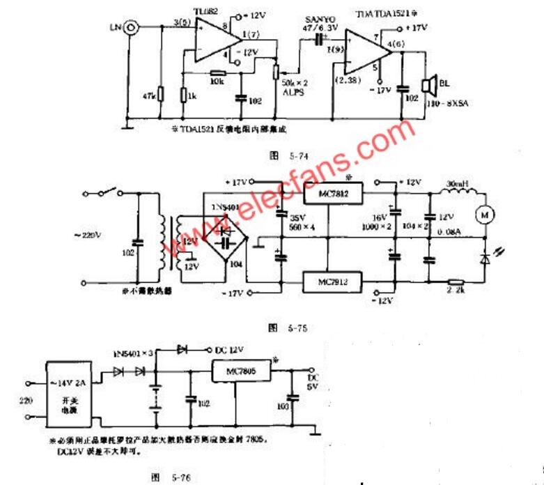
The music book is made by fixing the two South Whale YD-110-8SXA loudspeakers with the plastic shells of the car's top speakers. The number of strokes is 80~10000Hz. The actual low frequency is not deep but the response is fast, accurate and the vocals are good. In fact, the pitch of the instrument is not more than 8000Hz. Try to put Tchaikovsky's first - steel spears coupative "81812", feel the piano sound in most cases performance is more accurate, brass instruments can make you feel brilliant, artillery sound dive, sound pressure The grade is small but clear. The connection uses 30 yuan "gold and silver" lines of 1 yuan/meter. This speaker is the largest of the 4 inches of magnets, and is similar to some 6.5-inch magnets, and has a shield that can be used for mid-range or main voice into midrange.
The power supply adopts "UPS", a 14V/2A switching power supply generates all voltages, and is powered by a battery during a power outage (lights out). The circuit is shown in Figure 5-76. The battery capacity must not be lower than 4Ah. It can also drive an electricity at night. The fan blows, reading a small light bulb.
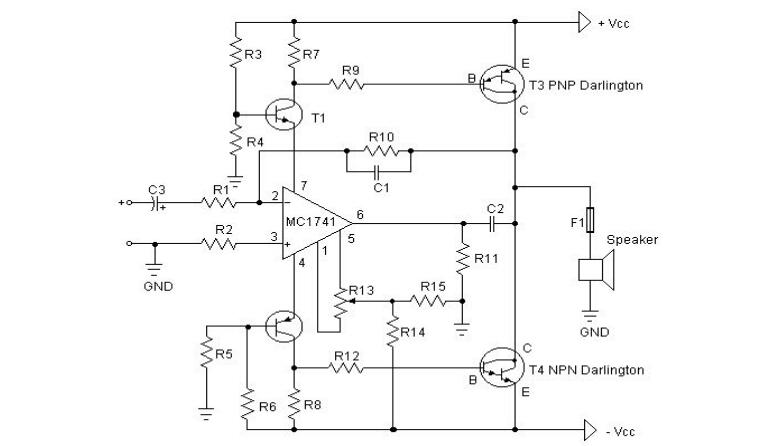
3, Hi-Fi power amplifier circuit with BOMExplanation note: - The first thing you need to do is test the amplification factor hfe or β of the last power tube. If their difference is greater than 30%, the amplifier will not give you a clear voice. I use the MJ3001 and MJ2501 transistors. Their difference is 5%.
Before starting up, you must short-circuit the input terminals. Connect an ammeter to the output of the amplifier. Then turn on the power and adjust R13 to make the ammeter current to microamps. If you are lucky enough, you may reach 0. The ammeter current is 10 micro. Amperage is very easy to do.
Power amplifier circuit diagram:
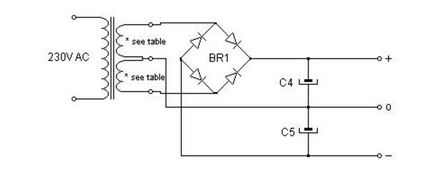
Power circuit:
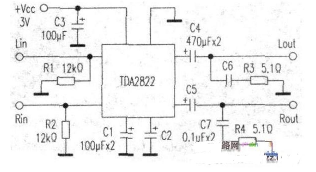
The amplifier uses the commonly used TDA2822 small power amplifier block (easily available on the market), TDA2822 is an 8-pin double inline plastic integrated block, small size, large output power. There is no need to add a radiator. The entire circuit components are few, the power supply voltage is DC 2V-15V, the quiescent current and distortion are very small, can work in the stereo state, can also work in the BTL state.
Circuit principle see the figure. All the components used in the figure are commonly used components. The resistance is 1/4W and the capacitance is 25V. This circuit is a two-channel circuit, Cl and C2 as a coupling capacitor, play blocking role, C3 is the power filter capacitor, C4, C5 is the output coupling capacitor, Rl, R2 is a bias resistor, R3, R4, C6, C7 role It is to prevent self-excitation. This circuit uses 3V DC power supply, if higher voltage can be used to increase output power, but the maximum must not exceed 15V. The speaker is 8Ω 1W or 4Ω 2W. The bigger the diameter, the better.
Battery Siren,Home Battery Siren,Battery Back Up Siren,Battery Back Up Alarm
NINGBO SANCO ELECTRONICS CO., LTD. , https://www.sancobuzzer.com