The color TV remote channel converter introduced in this paper adopts the RF output mode. As long as the cable input end of the color TV is connected to the RF output end of the converter with a cable outside the machine, the remote conversion channel and the remote control adjustment tone can be realized, and the screen can be The remote control information is displayed on the top. The finite noise sensitivity of the converter image channel is not inferior to 150μV in the VHF band, not worse than 250Lrvl in the UHF band, and the color sensitivity is not inferior to 75μV, and the automatic gain control is not less than 60dB. The converter can receive and store 32 TV programs, which brings great convenience to the function expansion of non-remote control ordinary color TVs that can only preset 8 channels.
working principle
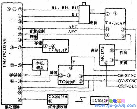
The block diagram of the converter is shown in Figure 1. Its remote control circuit uses Toshiba CTS-130A (microprocessor TMP47C433AN, memory TC89101P, screen display TC9020P) remote control system. The IF signal processing circuit uses TA7680AP, the infrared signal receiving circuit uses CX20106A, and the RF modulation circuit uses MC1374. The remote control transmitting circuit adopts TC9012F.
The remote control circuit and infrared receiving circuit of the converter are shown in the figure below.
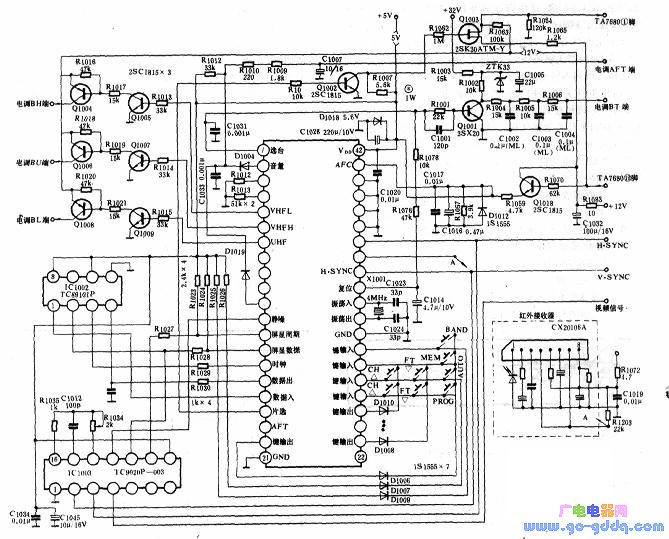
1. Microprocessor circuit (TMP47C433AN)
(1) Reset function and timing function The 33 pin of the TMP47C433AN is the reset terminal (RESET). When this pin is low, the microprocessor stops working and all outputs are reset to zero. When this pin is high, the microprocessor starts executing the program from the PC-O. 31, 32 feet are the crystal oscillator input and output terminals, providing timing pulses for the microprocessor.
(2) Channel selection function TMP47C433AN pin 1 is the tuning voltage output terminal, and the pulse width modulation signal of H: is sent, and is sent to the BT terminal of the electric tuner TDQ-3 as the tuning voltage. The 5, 6, and 7 pins are VI., VH, and U output terminals respectively. The output voltage is sent to the BL, BH, and BU terminals of TDQ-3 for frequency conversion. Pin 18 is the automatic frequency control output. The converter uses H. when searching for channels. SYNC and AFC signals, the search stops after the TV signal is detected. The output of this pin is "L" state, which makes AFT turn on; when there is no TV signal, the search continues, and the output of this pin is "H" state, which makes AFT disconnect.
(3) The analog control function 2 pin is the volume control output end, and the output pulse width modulation signal is sent to the 1 pin of TA7680 to control the maximum sound.
(4) The memory function 14 is the clock control terminal, and the 17 pin is the chip select signal output: the end, 15 and 16 are the data input terminals. The above legs are respectively connected to the 2, 1, 3, and 4 pins of the memory TC89101P to realize four-bit serial transmission of instructions, addresses, and data. TV festival and volume size information can be stored.
(5) The screen display function 12 feet is the graphic recognition signal output end. Pin 13 is the data output. Its 12~14 pins are connected to the 12th, 10th and 11th pins of the display circuit respectively, providing display cycle, data and clock pulses to TCP020P.
(6) The keyboard 20, 22~25 of the machine is the keyboard output end, and the 26~29 feet are the keyboard input end, which constitutes the keyboard control matrix. The 15th, 16th and 26th to 29th legs form the system function setting matrix.
(7) Other functions 11 feet are squelch output terminals, and the output signal is sent to the 1 pin of TA7680 to realize the squelch function. The 35 pin is the remote control signal input end, and the signal output by the infrared receiver CX20106A is sent to the main pin. 21 feet grounded, 42 feet connected to 10 sv power supply. Other features, the machine does not need.
2. Memory circuit (TC89101P)
The IC is an electrically erasable programmable read only memory for serial data transfer. The 1 pin is the chip select signal input terminal, the 2 pin is the clock input end, the 3 pin is the data input end, and the 4 pin is the data output end. The 6-pin is the storage selection terminal, and the foot is connected to +5v, so it constitutes 64×16 bits.
3. Screen display circuit (TC9020P)
The IC is a CMOS digital circuit for the control of TV screen character display. Since the converter is connected to the color television as an external radio frequency, the on-screen characters are achromatic. Pin 2 is the vertical sync input and pin 3 is the horizontal sync input. The 4 pin is the character brightness signal output end, and the output signal is mixed with the video signal of the 15-pin output of the TA7680 of the converter and sent to the 11th pin of the RF modulator MC1374. Pin 10 is the data input terminal, pin 11 is the clock input terminal, and pin 12 is the periodic signal input terminal, which receives the corresponding signals from the pins 13, 14, and 12 of the microprocessor. 13, 14 and 15 feet are connected to the RC oscillator.
4. Infrared signal receiving circuit (CX20106A)
The 1 pin of CX20106A is the remote control signal input terminal, and a photodiode is connected to the ground. The 2-pin external RC network is used to determine the frequency characteristics and gain of the internal amplifier. 3 feet external detection capacitor. An external resistor between the 5 pin and the power supply is used to set the center frequency fo of the band pass filter. When the external resistor 'is 200kΩ, fo=40kHz; when the external resistance is 220kΩ, f. =38kHz. 6 feet to the ground external integration capacitor. The 7-pin is the remote control signal output terminal, and the external power supply is connected to the 22kΩ resistor.
5. RF modulation circuit (MCl374)
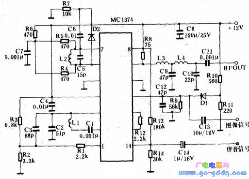
The RF modulation circuit of the converter is shown in the figure above, and the core part of the circuit is the integrated circuit MC1374. The lC is commonly used in radio frequency modulation circuits for color image signals of video recorders and color television sets.
Pin 1 of the MC1374 is an audio carrier input. 2, 3 feet external RC loop, with the internal circuit to generate audio carrier oscillation, and coupled to 1 pin through the RC series loop. 6, 7 feet external RF oscillation circuit. Pin 9 is the RF output. Pin 11 is the video signal input terminal and pin 14 is the audio signal input terminal. 12, 13 feet for the gain control terminal, adjust the size of the external resistor to change the modulation gain.
6. IF signal processing circuit (TA7680AP)
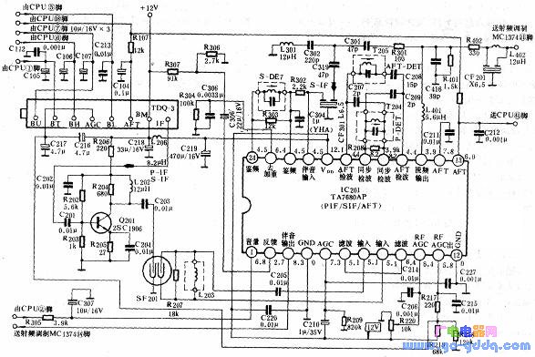
The IF signal processing circuit is shown in the figure above. The core device address of this circuit is the TA7680AP integrated circuit. This lc has been widely used in color TVs. This article only briefly introduces the parts related to the control circuit in the above figure.
The 1 pin of the TA7680AP is the volume control terminal, and the control signal output from the 2 pin of the microprocessor is superimposed on the pin. The audio signal output from pin 3 is capacitively coupled and sent to pin 14 of the RF modulator MC1374. The AFT voltage output from the 13-pin is filtered by the grounding capacitor to filter the pulsating component generated in the phase detection, and sent to the 41-pin of the microprocessor for searching and selecting the 甩. The video signal outputted by the 15-pin is filtered by the 6.5MHz notch filter and sent to the 11th pin of the MC1374 for RF modulation.
German type cable reel Non-rewirable, 230V~, IP20, Class I, with a thermal cut-out, with a non-rewirable plug with cord H05VV-F 3G1,0-1,5mm 2 ,
with 4-way socket outlet with or without shutters.
Germany Cable Reel,Cable Reel,Automatic Cable Reel,Cable Spool Reel
CIXI KYFEN ELECTRONICS CO.,LTD, , https://www.kyfengroup.com