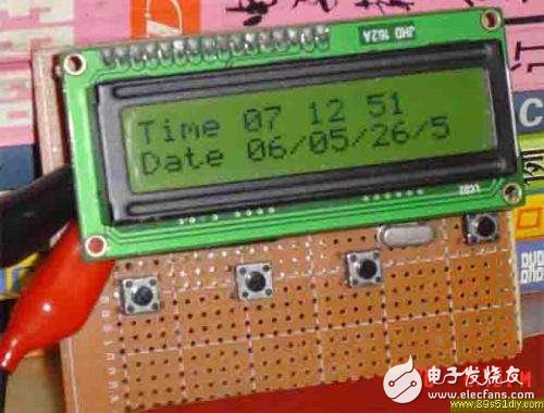
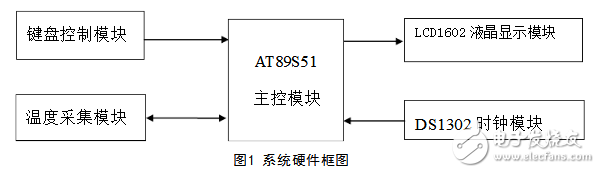
The electronic calendar system based on ds1302 mainly uses AT89S51 as the main control system in hardware selection ; DS1302 provides clock; DS18B20 as digital temperature sensor; LCD1602 LCD as display.
AT89C51 microcontroller
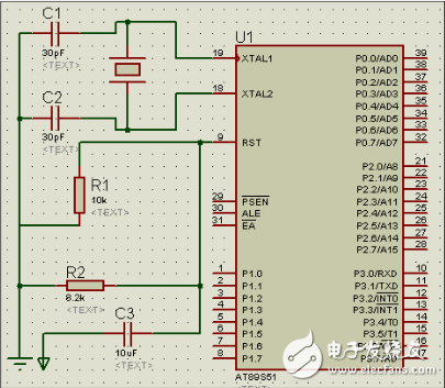
MCU minimum system
The AT89C51 MCU uses Flash ROM and has 4KB ROM storage space inside. The program space is completely sufficient compared to this design. It can work at 3V ultra-low voltage, and is fully compatible with MCS-51 series MCU, and it has ISP online programming technology when used in circuit design. When debugging the circuit, due to incorrect modification of the program or new program When the function needs to be burned into the program, the chip may be prevented from being damaged by multiple plugging and unplugging of the chip.
Ds1302
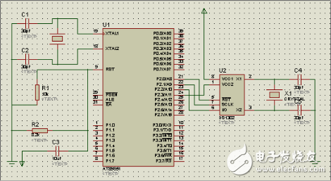
DS1302 and microcontroller connection
DS130 is a high-performance, low-power, real-time clock circuit with RAM from DALLAS. It can time the year, month, day, sun, hour, minute and second. It has leap year compensation function and working voltage. It is 2.5V to 5.5V. The three-wire interface is used for synchronous communication with the CPU, and multiple bytes of clock signals or RAM data can be transmitted at one time in a burst mode. The DS1302 has a 31&TImes;8 RAM register for temporarily storing data. The DS1302 is an upgraded version of the DS1202 that is compatible with the DS1202, but adds dual power pins for the main power/back power supply and provides the ability to charge the back power supply with a fine current. The main feature is the use of serial data transmission, which provides programmable charging for the power-down protection power supply and can turn off the charging function. A normal 32.768 kHz crystal is used. And DS1302 has the advantages of long service life and small error.
1602LCM dot matrix LCD screen
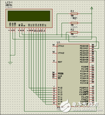
LCM1602 and microcontroller connection
LCD liquid crystal display, LCD display powerful, can display a large number of text, graphics, display diverse, clearly visible, for the electronic calendar, a 1602 LCD screen, the price is acceptable, the required interface line More, but it will bring a lot of convenience to debugging.
Digital Temperature Sensor DS18B20
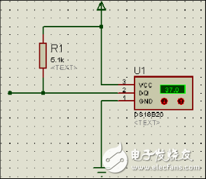
DS18B20 pin connection
This type of sensor is a digital sensor and requires only one data line for data transmission. It is easy to connect with a single-chip microcomputer, which can avoid A/D analog-to-digital conversion module, reduce hardware cost and simplify system circuit. In addition, the digital temperature sensor also has the advantages of high measurement accuracy and wide measurement range.
DS1302 principle and description(1) How the clock chip DS1302 works
The DS1302 must be initialized before each read and write program. The SCLK terminal is set to "0", then the RST terminal is set to "1", and the SCLK pulse is given. The read/write timing is as shown in Figure 7. Figure 6 shows the control word of the DS1302. Bit 7 of this control word must be set to 1. If it is 0, the DS1302 cannot be read or written. For bit 6, if RAM = 1 when reading/writing the program, CK = 0 when reading/writing the time. Bits 1 through 5 refer to the address of the operating unit. Bit 0 is the read/write operation bit, which is 1 when a read operation is performed; a 0 on this bit indicates that a write operation is being performed. The control byte is always input/output from the lowest bit. Table 2 shows the calendar and time register contents of the DS1302: “CH†is the clock pause flag. When this bit is 1, the clock oscillator stops and the DS1302 is in the low power state. When this bit is 0, the clock starts running. "WP" is the write protection bit and must be 0 before any writes to the clock and RAM. When "WP" is 1, the write protection bit prevents writes to any of the registers.
(2) Control word of DS1302
The control word of the DS1302 is shown in Figure 6. The high significant bit (bit 7) of the control byte must be a logic one. If it is 0, the data cannot be written to the DS1302. If bit 6 is 0, it means to access the calendar clock data, and 1 means to access the RAM data. Bit 5 to bit 1 indicate the address of the operating unit; the least significant bit (bit 0) if 0 indicates that a write operation is to be performed, and a value of 1 indicates that a read operation is performed, and the control byte is always output from the lowest bit.
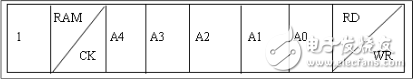
DS1302 control word
(3) Data input and output
At the rising edge of the next SCLK clock following the control instruction word input, data is written to the DS1302 and the data input begins with the low bit, bit 0. Similarly, the data of the DS1302 is read at the falling edge of the next SCLK pulse immediately following the 8-bit control instruction word, and the data is read from the lower 0 bits to the upper 7 bits.
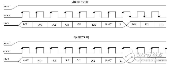
DS1302 read and write timing diagram
(4) Register of DS1302
The DS1302 has 12 registers, 7 of which are related to the calendar and clock. The stored data bits are in the form of BCD codes. The calendar, time register and its control words are shown in the figure.

DS1302 calendar, time register
In addition, the DS1302 has a year register, a control register, a charge register, a clock burst register, and a RAM-related register. The clock burst register can read and write all the contents of the registers except the charge register in one order. The DS1302 and RAM related registers are divided into two categories: one is a single RAM unit, a total of 31, each unit is configured as an 8-bit byte, and its command control word is C0H~FDH, where the odd number is a read operation. The even number is a write operation; the other is a RAM register in burst mode. In this mode, 31 bytes of all RAM can be read and written at one time, and the command control words are FEH (write) and FFH (read).
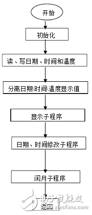
system designMain program flow chart
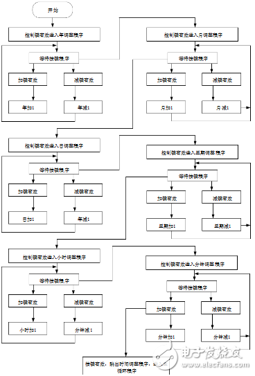
Time adjustment program flow chart
#include"reg51.h"
#define uint unsigned int
#define uchar unsigned char
Uchar a,miao,shi,fen,ri,yue,nian,week,key1n,temp;
#define yh 0x80
#define er 0x80+0x40
Sbit DQ = P3^5;
Sbit RS=P1^7;
Sbit E=P2^4;
Sbit RW=P1^6;
Sbit IO=P1^5;
Sbit SCLK=P1^4;
Sbit RST=P2^2;
Sbit ACC0=ACC^0;
Sbit ACC7=ACC^7;
Sbit key1=P1^0;
Sbit key2=P1^2;
Sbit key3=P1^3;
Uchar code tab1[]={"20 - - â€};
Uchar code tab2[]={" : : â€};
Void delay(uint xms)
{
Uint x,y;
For(x=xms;x"0;x--) ;
For(y=110;y"0;y--);
}
/ / LCD write command function
Write_1602com(uchar com)
{
RS=0;
RW=0;
P0=com;
Delay(1);
E=1;
Delay(1);
E=0;
}
/ / LCD write data function
Write_1602dat(uchar dat)
{
RS=1;
RW=0;
P0=dat;
Delay(1);
E=1;
Delay(1);
E=0;
}
/ / LCD initialization function
Lcd_init()
{
Write_1602com(0x38);
Write_1602com(0x0c);
Write_1602com(0x06);
Write_1602com(0x01);
Write_1602com(yh+1);
For(a=0;a"14;a++)
{
Write_1602dat(tab1[a]);
Delay(3);
}
Write_1602com(er+2);
For(a=0;a"8;a++)
{
Write_1602dat(tab2[a]);
Delay(3);
}
}
/***************DS1302About subfunctions********************/
/ / Write a byte
Void write_byte(uchar dat)
{
ACC=dat;
RST=1;
For(a=8;a)0;a--)
{
IO=ACC0;
SCLK=0;
SCLK=1;
ACC=ACC》1;
}
}
/ / Read a byte
Uchar read_byte()
{
RST=1;
For(a=8;a)0;a--)
{
ACC7=IO;
SCLK=1;
SCLK=0;
ACC=ACC》1;
}
Return (ACC);
}
/ / Write function to the 1302 chip, specify the write address, data
Void write_1302(uchar add,uchar dat)
{
RST=0;
SCLK=0;
RST=1;
Write_byte(add);
Write_byte(dat);
SCLK=1;
RST=0;
}
/ / Read the data function from 1302, specify the source address of the read data
Uchar read_1302(uchar add)
{
Uchar temp;
RST=0;
SCLK=0;
RST=1;
Write_byte(add);
Temp=read_byte(); SCLK=1;
RST=0; return(temp);
}
//BCD code to decimal function, enter BCD, return decimal
Uchar BCD_Decimal(uchar bcd)
{
Uchar Decimal;
Decimal=bcd》4;
Return(Decimal=Decimal*10+(bcd&=0x0F));
}
//1302 chip initialization subfunction (2012-06-26, 00:00:00, week2)
Void ds1302_init()
{
RST=0;
SCLK=0;
Write_1302(0x8e, 0x00);
Write_1302(0x80,0x00);
Write_1302(0x82,0x00);
Write_1302(0x84,0x00);
Write_1302(0x8a,0x02);
Write_1302(0x86,0x26);
Write_1302(0x88,0x06);
Write_1302(0x8c,0x12);
Write_1302(0x8e, 0x80);
}
/ / hour and minute display subfunction
Void write_sfm(uchar add,uchar dat)
{
Uchar gw,sw;
Gw=dat%10;
Sw=dat/10;
Write_1602com(er+add);
Write_1602dat(0x30+sw);
Write_1602dat(0x30+gw);
}
//year, month, day, display subfunction
Void write_nyr(uchar add,uchar dat)
{
Uchar gw,sw;
Gw=dat%10;
Sw=dat/10;
Write_1602com(yh+add);
Write_1602dat(0x30+sw);
Write_1602dat(0x30+gw);
}
/ / Write the week function
Void write_week(uchar week)
{
Write_1602com(yh+0x0c);
Switch(week
{
Case 1:
Write_1602dat('M');
Write_1602dat('O');
Write_1602dat('N');
Break;
Case 2:
Write_1602dat('T');
Write_1602dat('U');
Write_1602dat('E');
Break;
Case 3:
Write_1602dat('W');
Write_1602dat('E');
Write_1602dat('D');
Break;
Case 4:
Write_1602dat('T'
Write_1602dat('H');
Write_1602dat('U');
Break;
Case 5:
Write_1602dat('F');
Write_1602dat('R');
Write_1602dat('I');
Break;
Case 6:
Write_1602dat('S');
Write_1602dat('T');
Write_1602dat('A');
Break;
Case 7:
Write_1602dat('S');
Write_1602dat('U');
Write_1602dat('N');
Break;
}
}
//*Keyboard scan related function void keyscan()
{
If(key1==0)
{
Delay(9);
If(key1==0)
{
Delay(20);
While(!key1);
Key1n++;
If(key1n==9) key1n=1;
Switch(key1n)
{
Case 1:
TR0=0;
Write_1602com(er+0x09);
Write_1602com(0x0f);
Temp=(miao)/10*16+(miao)%10;
Write_1302(0x8e, 0x00);
Write_1302(0x80,0x80|temp);
Write_1302(0x8e, 0x80);
Break; case 2: write_1602com(er+6);
Break;
Case 3:
Write_1602com(er+3);
Break;
Case 4:
Write_1602com(yh+0x0e);
Break;
Case 5:
Write_1602com(yh+0x0a);
Break;
Case 6:
Write_1602com(yh+0x07);
Break;
Case 7:
Write_1602com(yh+0x04);
Break;
Case 8:
Write_1602com(0x0c);
TR0=1;
Temp=(miao)/10*16+(miao)%10;
Write_1302(0x8e, 0x00);
Write_1302(0x80,0x00|temp);
Write_1302(0x8e, 0x80);
Break;
}
}
}
If(key1n!=0)
{
If(key2==0)
{
Delay(10);
If(key2==0)
{
Delay(20);
While(!key2);
Switch(key1n) {
Case 1:miao++;
If(miao==60)
Miao=0;
Write_sfm(0x08,miao);
Temp=(miao)/10*16+(miao)%10;
Write_1302(0x8e, 0x00);
Write_1302(0x80,temp);
Write_1302(0x8e, 0x80);
Write_1602com(er+0x09);
Break;
Case 2: fen++;
If(fen==60)
Fen=0;
Write_sfm(0x05,fen);
Temp=(fen)/10*16+(fen)%10;
Write_1302(0x8e, 0x00);
Write_1302(0x82,temp);
Write_1302(0x8e, 0x80);
Write_1602com(er+6);
Break; case 3:shi++;
If(shi==24)
Shi=0;
Write_sfm(2,shi);
Temp=(shi)/10*16+(shi)%10;
Write_1302(0x8e, 0x00);
Write_1302(0x84,temp);
Write_1302(0x8e, 0x80);
Write_1602com(er+3);
Break; case 4:week++;
If(week==8) week=1;
Write_1602com(yh+0x0C);
Write_week(week);
Temp=(week)/10*16+(week)%10;
Write_1302(0x8e, 0x00);
Write_1302(0x8a,temp);
Write_1302(0x8e, 0x80);
Write_1602com(yh+0x0e);
Break; case 5: ri++;
If(ri==32)
Ri=1;
Write_nyr(9,ri);
Temp=(ri)/10*16+(ri)%10;
Write_1302(0x8e, 0x00);
Write_1302(0x86,temp);
Write_1302(0x8e, 0x80);
Write_1602com(yh+10);
Break;
Case 6: yue++;
If(yue==13)
Yue=1;
Write_nyr(6,yue);
Temp=(yue)/10*16+(yue)%10;
Write_1302(0x8e, 0x00);
Write_1302(0x88,temp);
Write_1302(0x8e, 0x80);
Write_1602com(yh+7);
Break;
Case 7:nian++;
If(nian==100) nian=0;
Write_nyr(3,nian);
Temp=(nian)/10*16+(nian)%10;
Write_1302(0x8e, 0x00);
Write_1302(0x8c,temp);
Write_1302(0x8e, 0x80);
Write_1602com(yh+4);
Break;
}
}
}
If(key3==0)
{
Delay(10);
If(key3==0)
{
Delay(20);
While(!key3);
Switch(key1n)
{
Case 1:miao--;
If(miao==-1)
Miao=59;
Write_sfm(0x08,miao);
Temp=(miao)/10*16+(miao)%10;
Write_1302(0x8e, 0x00);
Write_1302(0x80,temp);
Write_1302(0x8e, 0x80);
Write_1602com(er+0x09);
Break; case 2:fen--;
If(fen==-1)
Fen=59;
Write_sfm(5,fen);
Temp=(fen)/10*16+(fen)%10;
Write_1302(0x8e, 0x00);
Write_1302(0x82,temp);
Write_1302(0x8e, 0x80);
Write_1602com(er+6);
Break;
Case 3:shi--;
If(shi==-1)
Shi=23;
Write_sfm(2,shi);
Temp=(shi)/10*16+(shi)%10;
Write_1302(0x8e, 0x00);
Write_1302(0x84,temp);
Write_1302(0x8e, 0x80);
Write_1602com(er+3);
Break; case 4:week--;
If(week==0)
Week=7;
Write_1602com(yh+0x0C);
Write_week(week);
Temp=(week)/10*16+(week)%10;
Write_1302(0x8e, 0x00);
Write_1302(0x8a,temp);
Write_1302(0x8e, 0x80);
Write_1602com(yh+0x0e);
Break; case 5:ri--;
If(ri==0)
Ri=31;
Write_nyr(9,ri);
Temp=(ri)/10*16+(ri)%10;
Write_1302(0x8e, 0x00);
Write_1302(0x86,temp);
Write_1302(0x8e, 0x80);
Write_1602com(yh+10);
Break; case 6:yue--;
If(yue==0)
Yue=12;
Write_nyr(6,yue);
Temp=(yue)/10*16+(yue)%10;
Write_1302(0x8e, 0x00);
Write_1302(0x88,temp);
Write_1302(0x8e, 0x80);
Write_1602com(yh+7);
Break;
Case 7:nian--;
If(nian==-1) nian=99;
Write_nyr(3,nian);
Temp=(nian)/10*16+(nian)%10;
Write_1302(0x8e, 0x00);
Write_1302(0x8c,temp);
Write_1302(0x8e, 0x80);
Write_1602com(yh+4);
Break;
}
}
}
}
}
/ / timer, counter setting function
Void init()
{
TMOD=0x11;
TH0=0;
TL0=0;
EA=1;
ET0=1;
TR0=1;
}
/******************************* Delay function*************** *****************
* Function: It takes 24μs to call this function under the crystal condition of 11.059MHz, then 16μs for each count.
************************************************** ************************/
Void DS18_delay(int useconds)
{
Int s;
For (s=0; s "useconds; s++);
}
/******************************* Reset function ****************** ***************
* Function: Complete single bus reset operation
* The reset time is 480μs, so the delay time is (480-24)/16 = 28.5, taking 29μs.
* After 70μs, the pulse is detected, so the delay time is (70-24)/16 = 2.875, which is 3μs.
************************************************** ************************/
Unsigned char ow_reset(void)
{
Unsigned char presence;
DQ = 0;
DS18_delay(29);
DQ = 1;
DS18_delay(3);
Presence = DQ;
DS18_delay(25);
Return(presence);
}
/****************************** Bit write function ***************** ****************
* Function: Write 1 bit value to single bus: bitval
************************************************** ***********************/
Void write_bit(char bitval) { DQ = 0;
If(bitval==1) DQ =1;
DS18_delay(5);
DQ = 1;
}
/**************************** Byte write function ****************** ***************
* Function: Write a byte value to a single bus: val
************************************************** ***********************/
Void ds18write_byte(char val)
{
Unsigned char i;
Unsigned char temp;
For (i=0; i"8; i++) {
Temp = val》"i;
Temp &= 0x01;
Write_bit(temp);
}
DS18_delay(5);
}
/**************************** Bit Read Function ***************** ***************
* Function: Reading a bit signal from a single bus requires a delay time of 15μs, so the DS18_delay() function defined earlier* cannot be called, and a for() loop is used to implement the delay. *
************************************************** *********************/
Unsigned char read_bit(void)
{
Unsigned char i;
DQ = 0;
DQ = 1;
For (i=0; i "3; i++);
Return(DQ);
}
/**************************** Byte read function ****************** ***************
* Function: Read one byte value from a single bus *
************************************************** ***********************/
Unsigned char DSread_byte(void)
{
Unsigned char i; unsigned char value = 0; for (i=0;i"8;i++)
{
If(read_bit()) value|=0x01"i;
DS18_delay(6);
}
Return(value);
}
//******************* main function **************************
Void main() { lcd_init();
Ds1302_init();
Init();
Delay(80);
While(1)
{
Keyscan();
}
}
/ / Get and display the calendar and time
Void TImer0() interrupt 1
{
Miao = BCD_Decimal(read_1302(0x81));
Fen = BCD_Decimal(read_1302(0x83));
Shi = BCD_Decimal(read_1302(0x85));
Ri = BCD_Decimal(read_1302(0x87));
Yue = BCD_Decimal(read_1302(0x89));
Nian=BCD_Decimal(read_1302(0x8d));
Week=BCD_Decimal(read_1302(0x8b));
Write_sfm(8,miao);
Write_sfm(5,fen);
Write_sfm(2,shi);
Write_nyr(9,ri);
Write_nyr(6,yue);
Write_nyr(3,nian);
Write_week(week);
}
Yellow Led Display,0.36 Inch Yellow Led Display,3 Digits Green Led Display,3 Digits Led Segment Display
Wuxi Ark Technology Electronic Co.,Ltd. , https://www.arkledcn.com