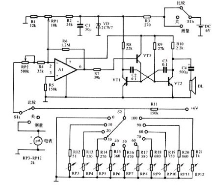
In the figure, a total of 10 resistors from R12 to R21 and a voltage divider formed by R11 produce a relatively accurate reference voltage, which can produce 11 reference tones, which is equivalent to 10 scales of 0~10 on the voltmeter dial. . The resistance values ​​should be accurate and calibrated to correspond to the measurement range of 0~100mV. The voltmeter has a total of 11 scales of 0, 10, 20, 30, 40, 50, 60, 70, 80, 90, 100mV.
The transistors VT1, VT2 (both 3DG6) form a simple square wave audio oscillator whose frequency is controlled by the voltage of the transistor VT3 (3CG4). Operational amplifier A1 (F007) drives transistor VT3. Potentiometer RP1 regulates the gain of the operational amplifier. Adjust the sensitivity potentiometer RP2 and the frequency potentiometer RP3~RP12 so that the frequency of the voltage controlled oscillator can keep up with the change of the measured voltage, and no matter which scale of the voltmeter, when the switch S1 is set to "measure" and " When you compare the position, the sound you hear is the same.
After the circuit is installed and checked, the adjustment can be made. First, set S2 to 0, S1 to "Compare" position, disconnect C4 of VT2 collector, connect the frequency meter to the collector of VT2, and connect with S2 in parallel. Millivolt table. Then adjust the potentiometer RP2, so that the oscillation frequency of the voltage controlled oscillator is 400Hz, and the reading of the millivolt meter is 0V.
Then dial S2 to the remaining gears and adjust the potentiometers RP3~RP12 accordingly so that the millivoltmeter readings are 10, 20, 30, 40, 50, 60, 70, 80, 90, 100mV, respectively. The voltmeter reading determines approximately 500 Hz, 600 Hz, 700 Hz, 800 Hz, 900 Hz, 1000 Hz, 1100 Hz, 1200 Hz, 1400 Hz, and 1600 Hz.
It is an important part of VFD (Vacuum Fluorescent Display), and its role is to install the grid and filament position, and the pins are the circuit board for VFD installation. It can be widely used in automotive VFD panel, home appliance VFD panel, audio, VTR VFD panel, VFD panel for transaction machine, VFD panel for measuring instrument, VFD panel for communication equipment, etc.
Sewing Machine Accessories,No Burr Sewing Machine Accessories,Etching VFD Linkage,High Precision VFD Acessories
SHAOXING HUALI ELECTRONICS CO., LTD. , https://www.cnsxhuali.com