The entire system in the solution can be powered by a 9V battery, enabling low power and portable functions. AC measurement is measured by converting the AC signal into DC voltage with the AD637 true RMS conversion chip; input voltage conversion is performed with an inverting amplifier with clamp protection, achieving 10MΩ input impedance and high safety. The key components in the circuit use TI's precision operational amplifier OPA07 and instrumentation amplifier INA128 to achieve high-precision measurement. The ADC uses STM32f103ZET6 on-chip 12-bit AD to achieve low power consumption and automatic range switching.
0 Preface
In smart instruments, automatic range conversion technology is often used, which allows the instrument to automatically select the most appropriate range for high-precision measurement in a short period of time. The implementation of autoranging is generally achieved by controlling the attenuation amplification of the input signal. In terms of the voltmeter, the input measurement voltage is greater than the input range of its AD converter, so its range switching is basically the process of signal attenuation multiple switching.
1. System overall plan and working principle
System function block diagram shown in Figure 1. STM32F103ZET6 processor is the core device of this system, which is responsible for controlling the normal operation of the whole system, including reading the result of AD conversion and control of 200mV and 2V gear position; button input action response; segment LCD drive; range automatic conversion control Wait.
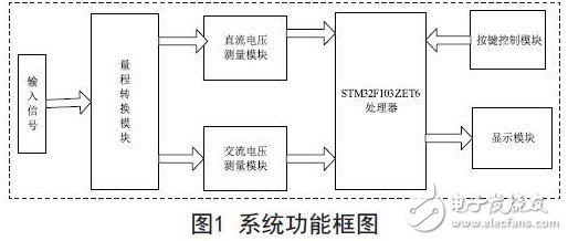
The input voltage signal passes through the range conversion module and becomes a voltage that can be sampled normally by the ADC analog input. The function of the AC voltage measurement module is to convert the measured AC voltage to the corresponding RMS value. The function of the key input is to input various values ​​when switching between different measurement modes and calculating the relative error.
2. System hardware structure
(1) Power management hardware circuit
The system has a low power consumption mode, that is, it does not operate within a certain period of time, and the system automatically cuts off the working power of a part of the circuit under the control of the single chip microcomputer. The schematic diagram of the power management circuit is shown in Figure 2.
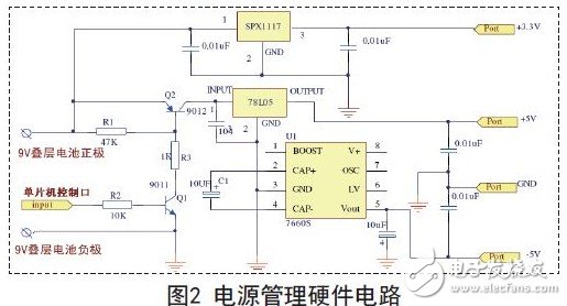
The positive pole of the battery is divided into two ways. The first way is directly connected to the input terminal of SPX1117. The SPX1117 is a three-terminal integrated voltage regulator chip, and its output terminal outputs a constant 3.3V, which is used as the power supply of the single chip system. The other way is through the transistor 9012 can be switched and controlled. In this design, when the system is in normal working state, the single-chip control port outputs a high level, 9011 is in a saturated state, the base voltage of 9012 is close to the ground voltage, 9012 is saturated, that is, it is in the guide Pass status. The positive voltage of the 9V laminated battery reaches the input of the 78L05 three-terminal integrated voltage regulator chip, and its output terminal outputs a stable +5V voltage. -5V is generated by the negative pressure charge pump 7660S. When the system is in the "low power" state, the output of the microcontroller control port is low. 9011 is in the off state, the base voltage of 9012 is 9V, and it is also in the off state, and the analog part of the power supply voltage is zero. The microcontroller will always be in a different mode of operation.
(2) AC voltage conversion circuit
AC voltage measurement true RMS conversion circuit is a key part of measuring AC voltage, its design directly affects the measurement accuracy of AC voltage signal. In this design, we choose to use AD637 to achieve AC signal to DC quantity. The transformation, the circuit is shown in Figure 3.
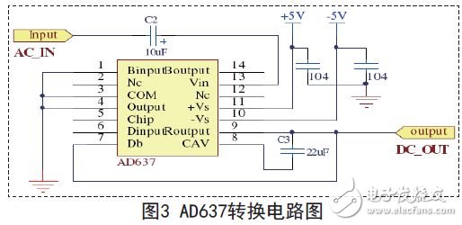
AC_IN is the AC voltage input terminal, and DC_OUT terminal outputs the DC voltage signal. The value of the output DC voltage is the true rms value of the input AC voltage. This circuit completes the AC to DC conversion. During the experimental test, it was found that the conversion effect for the 5000Hz AC signal is still good.
(3) Range conversion circuit
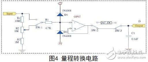
The range conversion of this system is realized by single-chip microcomputer control analog switch and relay. The principle block diagram is shown in Figure 4.
10 inch tablet is the most important size on tablet market. Which kind of clients like more? The answer is loving bigger size or storage, longer working time, etc. Since Android Tablet 10 inch is usually equipped with full HD screen, memory support up to 8GB, storage up to 256GB, battery up to 7000mAh-working 5-8hours. However, 8 inch android tablet mainly up to 4GB ram 64GB ROM, 4000mAh battery. At this store, you can see more than ten different 10 inch tablets on sale and one 10 inch windows tablet with magnetic keyboard option, and high level CPU and SIM Card option. Besides, you can also see amazon tablet 10 inch with competitive cost, especially take above 1000pcs. Except android tablet, 14 inch 64Gb Student Laptop for online learning, 15.6 inch celeron n5095 business laptop, 15 inch intel i3, i5, i7 10th or 11th generation Gaming Laptop and 16 inch laptop with 4gb graphics card and 16gb ram 512GB ssd alternatives also.
Any other special requirements, just fee free to contact us. Will try our best to support you.
10 Inch Tablet,10 Inch Tablets On Sale,Android Tablet 10 Inch,Amazon Tablet 10 Inch,10 Inch Windows Tablet
Henan Shuyi Electronics Co., Ltd. , https://www.shuyiminipc.com