A programmable controller (PLC) is a control device for digital operations and operations. As an alternative to traditional relays, PLC is widely used in various fields of industrial control. Because PLC can use software to change the control process, it has the characteristics of small size, flexible assembly, simple programming, strong anti-interference ability and high reliability, especially suitable for operation in harsh environments.
1. Input of switch command signal
The input signal of the inverter includes a switch type command signal that operates on the running state of running/stopping, forward/reverse, jog, and the like. The inverter usually uses a relay contact or a component with a relay contact switch characteristic (such as a transistor) to connect to the PLC to obtain an operating status command, as shown in Figure 1.
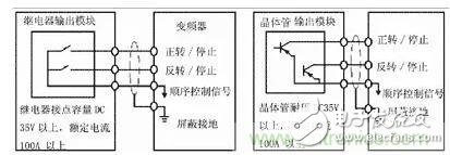
Figure 1. Connection of the running signal
When using relay contacts, it often causes malfunction due to poor contact; when using transistors for connection, it is necessary to consider the voltage and current capacity of the transistor itself to ensure the reliability of the system.
When designing the input signal circuit of the inverter, it should also be noted that when the input signal circuit is not connected properly, it sometimes causes the inverter to malfunction. For example, when the input signal circuit uses an inductive load such as a relay, the noise caused by the surge current generated by the relay opening and closing may cause the inverter to malfunction, and should be avoided as much as possible. Figure 2 and Figure 3 show examples of correct and incorrect wiring.
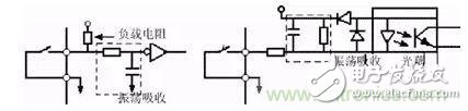
Figure 2. Inverter input signal access method
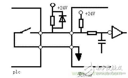
Figure 3. Error connection of the input signal
When the input switch signal enters the inverter, crosstalk between the external power supply and the inverter control power supply (DC24V) sometimes occurs. The correct connection is to use the PLC power supply to connect the collector of the external transistor to the PLC via a diode. As shown in Figure 4.
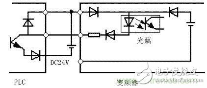
Figure 4. Input signal anti-jamming connection
2. Input of numerical signals
There are also some input types of numerical signals (such as frequency, voltage, etc.) in the inverter, which can be divided into digital input and analog input. The digital input is mostly given by the keyboard operation and serial interface on the inverter panel; the analog input is externally given through the terminal, usually input by 0~10V/5V voltage signal or 0/4~20mA current signal. . Since the interface circuit varies depending on the input signal, the output module of the PLC must be selected according to the input impedance of the inverter. Figure 5 shows the signal connection between the PLC and the inverter.  
When the voltage signal range of the inverter and PLC is different, for example, the input signal of the inverter is 0~10V, and the output voltage signal range of the PLC is 0~5V; or the output signal voltage of one side of the PLC is 0~10V. When the input voltage signal range of the inverter is 0~5V, due to the limitation of the allowable voltage and current of the inverter and the transistor, it is necessary to connect the current limiting resistor and the voltage dividing method in series to ensure the opening and closing. Does not exceed the corresponding capacity of the PLC and the inverter. In addition, the wiring should be separated when wiring, to ensure that the noise on the side of the main circuit is not transmitted to the control circuit.   
Usually, the inverter also outputs a corresponding monitoring analog signal to the outside through the Terminal Block. The range of electrical signals is typically 0 to 10V/5V and 0/4 to 20 mA current signals. In either case, it should be noted that the input impedance of the PLC side must be such that the voltage and current in the circuit do not exceed the allowable value of the circuit to ensure system reliability and reduce errors. In addition, since the components of these monitoring systems are different from each other, it is necessary to consult the manufacturer if there is any unclear.  
In addition, when using the PLC for sequential control, since the CPU takes time to perform data processing, there is a certain time delay, so it should be considered in more precise control.  
Because the inverter will generate strong electromagnetic interference during operation, in order to ensure that the PLC does not malfunction due to the noise generated by the main circuit breaker and switching device of the inverter, the inverter will be converted.
The following points should be noted when connecting the PLC to the PLC:
(1) The PLC itself should be grounded according to the specified wiring standards and grounding conditions, and care should be taken to avoid using the common grounding wire with the inverter, and to make the two separate as much as possible when grounding.  
(2) When the power supply condition is not good, connect the noise filter and the transformer for noise reduction to the power supply module of the PLC and the power supply line of the input/output module. In addition, if necessary, on the inverter side. Corresponding measures should also be taken.  
(3) When the inverter and PLC are installed in the same operating cabinet, the wires related to the inverter and the wires related to the PLC should be separated as much as possible.  
(4) Improve the level of noise interference by using shielded wires and twisted pairs.
When the PLC and the inverter are connected to the application, since the two are related to the use of weak current to control the strong electricity, attention should be paid to the interference that occurs during the connection, to avoid malfunction of the inverter due to interference, or damage to the PLC or the inverter due to improper connection. .
Solder Cup Waterproof D-Sub Connector
The Solder Cups D-sub connector, also known as Solder Cups D-sub connector , typically contains a pin layout of 9 pin, 15 pin, 25 pin, 37 pin & 50 pin positions housed in increasing shell sizes accordingly. They are available in both male (plug) and female (socket) variants with the male signal contacts/pins (current rating of 5A) spaced every 2.76mm in horizontal rows and the spacing of rows vertically at 2.84mm laid out half the distance between pins of existing rows.
IP66 IP67 Rated Waterproof D-Sub Panel Mount Solder Connectors
Harsh outdoor or indoor environments can destroy electronic equipment. Standard D-sub connectors are not intended to withstand contaminants such as water and dust. These waterproof solder cup connectors are available in male or female genders and DB9, DB15, DB25, and HD15 sizes. They will accommodate wire ranges from 30 - 20 AWG. Construction features gold plated brass contacts, nickel plated steel shells, and a silicone insulating ring. Maximum recommended panel thickness is 0.078".
Antenk offer a wide range of waterproof standard density and high density male and female high density D-Sub connectors solder cup with stamped and formed Contacts in cable mount used in a variety of demanding applications.
Antenk's Solder Cup D-Sub Connectors Stamped contacts
FEATURES
Solder cup d-subs available in industry sizes/positions
Low cost economy series.
Nickel shells have indents to provide grounding and additional retention.
Low cost & high performance, non-removable stamped contacts.
Optional mounting hardware available.
Antenk's SOLDER CUP D-SUB CONNECTORS Stamped contacts
MATERIALS
Shell: Steel, Tin or Nickel Plated
Insulator: Glass-filled thermoplastic. U.L. rated 94V-O
(230°C process temp)
Stamped contacts: Male pins - Brass | Female pins - Phosphor bronze
Plating: Gold flash on entire contact (contact us for other plating options)
Solder Cup Waterproof D-Sub Connector Stamped & Formed Contact, Solder Cup Waterproof D-Sub Connector Machined Contacts, Waterproof Panel Mount Solder Cup D-Sub Connector
ShenZhen Antenk Electronics Co,Ltd , https://www.pcbsocket.com