EDA dual whip antenna and matching network design
With the application of frequency hopping, spread spectrum and other technologies in modern military communication systems, it has become an important topic in antenna research to find wide-band, omnidirectional, miniaturized and shared antennas. It is difficult to meet the above requirements simply by relying on the structural design of the antenna. As the front-end component of the communication equipment, the antenna plays a vital role in the communication quality.
People use a variety of measures to improve the performance of the antenna, loading is a typical technology to adapt to this miniaturized antenna. The use of antenna broadband matching network is an effective technology to further improve antenna broadband technology. This article takes 120-520 MHz working frequency as an example, selects the appropriate loading position according to the limited antenna structure data, and uses software optimization to obtain a reasonable loading value and an optimized matching network.
1 Antenna and matching network model
The model of the antenna is shown in Figure 1. The loading method uses a lossless parallel LC circuit. The matching network is located at the bottom of the antenna and uses a hybrid network, as shown in Figure 2.
2 Antenna and matching network analysis
2.1 Loading position of the antenna
The antenna is a lumped double whip antenna, and the model is built on an ideal conductive ground. The purpose of loading is to make the antenna obtain the traveling wave current and reduce the reflection. The loading at this time is the best loading. Discussed here is the lossless loading, the relationship between the optimal loading position of the reactance loading and the reactance is: 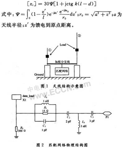
2.2 Matching network analysis
The input impedance zin of the antenna can be obtained from the current distribution. Looking at the feeder end, the input impedance of the entire system is: 
3 EDA software optimization design
The optimization design of antenna related parameters adopts CST software. According to actual requirements, our optimization parameters include loading position h and antenna spacing d. From the data obtained from the optimization, the actual model of the antenna is designed. The impedance data obtained from the test is imported into the ADS software as the basis for matching network parameter optimization. The structure of the matching network is not used as an optimization variable. Optimization parameters include matching network component values.
4 Calculation results and analysis
Considering the actual required antenna frequency bandwidth, from tens of MHz to hundreds of MHz, the structure size of the antenna is: h1 = 150 cm, h2 = 30 cm, r = 1 cm, and the optimized antenna loading position is: h3 = 24.5 cm, antenna spacing d = 58.9 cm. According to this data, make a physical model and import the test data into the ADS software. The optimized component values ​​are shown in Table 1. 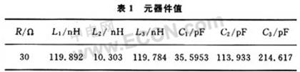
According to the optimized data, in the case where the matching network is not connected, the obtained standing wave is shown in FIG. 3. It is found through graphics that most of the standing wave ratios are above 2, so it must be improved by accessing the matching network. 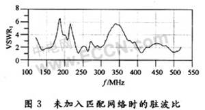
Figure 4 is the VSWR after accessing the matching network. It can be seen from Fig. 4 that the standing wave ratio has been well controlled below 2. 
Figure 5 shows the relationship between matching network efficiency and operating frequency.
It can be seen from the above series of figures that the addition of the matching network makes the antenna have good broadband performance within 120 ~ 520 MHz, the port standing wave ratio is below 2.0, and also due to the introduction of the matching network, especially the resistance R1 Join, so that the gain of the antenna is affected. But through the optimization of EDA software, while maintaining the bandwidth, try to improve the working efficiency of the matching network, so that in this band, the working efficiency of the matching network has basically reached more than 70%.
5 Conclusion
A short-wave ultra-wideband dual-whip antenna is introduced here. In order to obtain a better standing wave ratio and gain in the frequency band, a reasonable matching network is designed. Using the EDA simulation software optimization tool, the loading position of the antenna was optimized, and parameters such as network component values ​​were matched, and good results were obtained.
Mini Industrial Pc,Industrial Mini Pc,Fanless Indutrial Pc,Industrial Computer,Embedded Industrial PC
Shenzhen Innovative Cloud Computer Co., Ltd. , https://www.xcycomputer.com