introduction
This article refers to the address: http://
Automobile exhaust has become one of the main sources of urban air pollutants. Governments at all levels have taken comprehensive measures from different aspects such as development planning, urban construction and energy supply to alleviate the impact of vehicle exhaust emissions on the atmospheric environment. Relevant departments are also studying and formulating policy measures to promote the establishment of a more convenient and efficient public transportation system and reduce energy consumption and exhaust emissions in the transportation industry. The mobile vehicle exhaust gas analyzer is a testing device designed to detect the exhaust emission index of a car during driving. It will play a role in controlling exhaust emissions and establishing a low-carbon life.
Mobile car exhaust analyzer
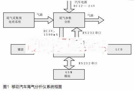
When the car is started, the mobile vehicle exhaust gas analyzer starts the air pump to sample the exhaust gas from the exhaust pipe of the automobile, and then enters the gas analysis component IRidium100 through dust removal, oil removal and water filtration treatment, and performs internal infrared processing to collect CO, CO2, HC. The concentration data, then the exhaust gas enters the external O2, NOx sensor, and collects the exhaust gas concentration data of the corresponding O2 and NOx. These data are digitally detected after signal detection, amplification, and processing, and are transmitted to the microprocessor through the IR-Series' RS-232 serial port. The microprocessor is processed and stored by statistical, averaging and other algorithms, and is encapsulated according to a customized environmental communication protocol, and transmitted to a designated upper management platform through GSM/GPRS/CDMA data communication or short message communication. There is an operation menu on the LCD on the analyzer. The user can perform menu operation through the keyboard, and the working status of the device and the analysis result of the exhaust gas can be obtained. The specific detection data results of CO, CO2, HC, O2 and NOx can be displayed on the LCD. The structure of the mobile car exhaust gas analyzer is shown in Figure 1.
Hardware design of mobile automobile exhaust gas analyzer
The gas analysis component of the exhaust gas analyzer uses the IRidium 100 gas analysis module of CITY, UK. It collects the concentration data of CO, CO2 and HC by internal infrared processing. The IRidium100 can obtain O2 and NOx concentration data through an external O2 sensor and NOx sensor.
The MCU system uses C8051F020, which has two serial ports, one of which is connected to the IRidium100, and the other serial port is connected to the GSM/GPRS or CDMA communication module. The data is exchanged with the customized communication protocol and the upper management platform.
The input power is directly connected to the car power supply DC12V ~ DC24V, converted to DC12V to the Iridium100, and a set of DC5V power supply output to the microcontroller and communication module.
The MCU controls the operation of the sampling pump through the relay, and mainly controls the action of the intake and exhaust. The relay controls the air pump, which is normally in the off state. When the system starts the exhaust gas analysis, the relay is energized to operate the pump for 5 minutes.
The GSM module uses the MC37I from Siemens. The module is a fully functional mobile communication industrial module. The CPU controls and transmits data through the serial port, and can transmit data including SMS, CSD, GPRS, and the like. The CPU controls the module using the AT command, which complies with the ETSI standards GSM 07.07 and GSM 07.05.
Software Design of Mobile Automobile Exhaust Gas Analyzer
Exhaust gas analyzer working mode
The dedicated vehicle exhaust analyzer design has four modes of operation:
1 manual working mode, in the power-on state, through the keyboard control menu, perform a process of exhaust gas analysis;
2 automatic working mode, when the time set every day is reached, the exhaust gas analysis process is automatically executed;
3 command working mode, when receiving the command of the upper management platform, perform an exhaust gas analysis process;
4 Calibration working mode, enter through the menu in the power-on state, and perform an exhaust gas calibration process.
Among them, the manual working mode and the calibration working mode are triggered by the key menu provided by the LCD in the field, and then the corresponding control commands are executed.
Manual operation mode, when you need to perform exhaust gas analysis immediately, manually enter the main menu selection, then select one exhaust gas detection, or choose to perform n exhaust gas detection (n input by the menu setting option), one or more exhaust gas analysis processes .
The automatic working mode is compared with the real-time clock in the RTC, and the real-time clock in the RTC is compared. After the time is equal, it is triggered to perform an exhaust gas analysis process. The automatic working mode is the default mode.
The command working mode is triggered by the command issued by the upper management platform, and the corresponding tail gas analysis process is executed. In the command working mode, the instrument receives the “acquisition exhaust†remote command from the communication module through the serial port, and the instrument automatically performs an exhaust gas analysis process.
Calibration operation mode, when the first power-on state or calibration demand, the air pump inlet is connected to the standard exhaust gas, manually enter the main menu to select the calibration process, and a calibration process is performed. The calibrated exhaust gas analyzer calibrates the reference test reference point to improve the accuracy of the exhaust gas detection.
Key command sequence selection for exhaust gas analysis module
According to the IRidium100 manual, the key command sequence for data acquisition of the CITY IRidium100 exhaust gas analysis module is as follows.
Range calibration of exhaust gas analyzer
1RESET (command number: $30), use this command before calibrating the exhaust gas analyzer. After the reset command is issued, the response is received and the reset is successful.
2ZERO ($35), zero calibration before the acquisition, start the pump for half a minute and then send the zero command. After receiving the zero calibration within 1 minute, the zero calibration is successful. At this time, the pump is stopped.
3SPAN SPECIFIED CHANNELS ($36), calibrated range command. After the completion of the zero calibration, the exhaust standard gas is manually connected, and the calibration operation is performed. At this time, the air pump is started, and after 15 seconds of ventilation, the calibration command is sent to the exhaust gas analysis module, and the LCD displays the instantaneous value, and stops the operation of the air pump after receiving the calibration completion response. At the same time, stop the operation of the serial port.
The collection of exhaust gas data, that is, an exhaust gas analysis process
1RESET ($30), this command is issued before each execution of the exhaust analysis command. The reset is successful after receiving a reset command.
2ZERO ($35), zero calibration before the acquisition, start the pump for half a minute and then send the zero command, and the calibration is completed after 1 minute. At this point, the pump operation is stopped.
3COMPENSATED DATA ($31), after the completion of the zero calibration, the data can be collected. First, let the pump run for half a minute and then send the data acquisition command. After 10 seconds, collect the data again and collect a group every 10 seconds. The LCD displays the instantaneous value, and after the acquisition process is completed (acquisition of 5 times of data), the average value is calculated as the final display. When the acquisition is completed 5 times, the operation of the serial port is stopped, and the operation of the air pump is stopped.
Software process design and implementation
The basic logic of the program flow is that the main program is triggered according to the conditions in the four working modes, and sends the corresponding command to the CITY IRidium100 exhaust gas analysis module. After executing the command, the module returns the execution result/status data. The main program displays the result data on the LCD on the one hand, and transmits it to the communication device on the other hand, and transmits it to the upper management platform by the communication device.
When the command of the upper management platform is received, or when the keyboard triggers the manual execution of the exhaust gas detection, or when the automatic detection time is reached, the action of executing the exhaust gas detection is started. After the exhaust gas analysis process, set the flag that has been tested that day.
The main menu of the LCD is as follows. The keyboard menus are operated by the up, down, +, -, and acknowledgment keys, and the corresponding commands are triggered.
"1.Show Settings", //Parameter display
"2.Setup", / / ​​parameter settings
"3.Analysis 1 time", //Manual execution of exhaust gas detection
"4.Analysis n times", //Manual execution of exhaust gas detection
"5.Calibration Zero", //zero
"6.Calibration Span", //scaling
"7.Show Date/Time", //Show RTC time
"8.Setup Date & Time", //Set RTC time
"9.Factory Default", //Restore the default detection range
"10.RETURN", //return
The result data measured in the four working modes are sent to the communication module through the serial port. The test result data format is as follows:
"CO = xx.xx%; CO2 = xx.xx%; HC = xxxxxppm; O2 = xx.xx%; NOx = xxxxxppm;".
Conclusion
This design uses the C8051F020 as the core single-chip system to control the Iridium 100, realizes the detection of CO, CO2, HC, O2, NOx concentration in the vehicle exhaust, and transmits the detected concentration data to the remote upper management platform through SMS data transmission. . The prototype of the design was tested in the environmental protection bureau of a certain place in Xinjiang, and the data of the field test was approved by the environmental protection department.
ESEN Optoelectronics Technology Co., Ltd, , https://www.esenoptoelectronics.com