Figure 2 is a schematic diagram of the operation of the headphone control function. When no headphone plug is connected to the jack, the R1-R2 voltage dividing resistor makes the voltage supplied to the HP-IN pin (16 pin) approximately 50mV, and drives Amp1B and Amp2B to work. To make the HWD2163 work in bridge mode. The output coupling capacitor isolates the half supply DC voltage to protect the headphones.
The voltage at the input HP-IN pin is 4V. When the HWD2163 is operating in bridge mode, the voltage across the load is essentially 0V. Therefore, even in an ideal state, it is difficult to cause the amplifier to operate in a single-terminal output mode. Connecting the headphone jack to the headphone jack separates the headphone jack from -OUTA and connects R1 to the HP pin to VDD. In this way, the headphone off function turns off the Amp2A and Amp2B and the bridge-connected speakers do not work. The amplifier drives the headphone with the output coupling impedance of R2 and R3. When the headphone impedance is 32Ω, the output coupling impedance is R2. The effect of R3 on the output drive capability of the HWD2163 is negligible.
This article refers to the address: http://
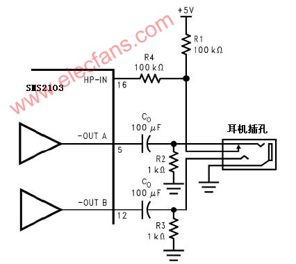
Figure 2 is also a schematic diagram of the electrical connection relationship of the headphone jack. The jack is a set of three-wire plug design. The tip and the ring are respectively a signal output of the stereo two-channel, but the outermost ring is ground. When the headphones are connected, a headphone jack with a console connection is sufficient to drive the HP-IN pin. A microprocessor or switch can replace the function of the control terminal in the headphone jack. The microprocessor or switch provides 4V~VDD voltage to the HP-IN, so the bridge mode connecting the speakers stops working and the Amp1A and Amp2A drive the headphones respectively. Left and right channels.
High Voltage Linear Power Supplies
HVLP series Linear High Voltage Power Supplies are High-voltage DC Power Supplies that achieve AC/DC conversion through power frequency transformers and transistor loop control. Compared with switching high voltage power supplies, linear high-voltage power supplies have higher stability, higher accuracy, and lower output ripple. And the most important, because of the use of the power frequency AC/DC conversion principle, the linear power supply has no high-frequency radiation interference, and it is especially suitable for use in places with restrictions on EMC and EMI.

The whole series linear power supply adopts industrial-grade metal chassis, pure copper AC/DC multi-insulation high-voltage transformer with varnish treatment, high-reliability multi-transistor filter loop, ensuring the power supplies can run for a long time at full load with high stability, high accuracy, and ultra-low ripple electronic characteristics, equipped with a complete protection circuit, which can better ensure the reliability of the linear power supply itself and the safety of the customer's load.
The output voltage and current can be adjusted by the 10-turn potentiometer with scale and lock on the front, equipped with 4 1/2-digit high-resolution LED meters for output value reading, and RS communication interface can also be added for remote control and monitoring of linear power supplies.
This series of linear high voltage power supplies are mainly used for gas discharge, high-voltage electronic tubes, and can also be applied for other electronic components burn-in test.
Because the output this power supply has HV, the output MUST be connected to the chassis for fixed grounding to ensure the personal safety of the user.
High-voltage Linear Power Supplies,Linear High Voltage Power Supplies, HV Linear Power Supplies, Linear HV Power Supplies, Linear HVPS
Yangzhou IdealTek Electronics Co., Ltd. , https://www.idealtekpower.com