 0 Preface
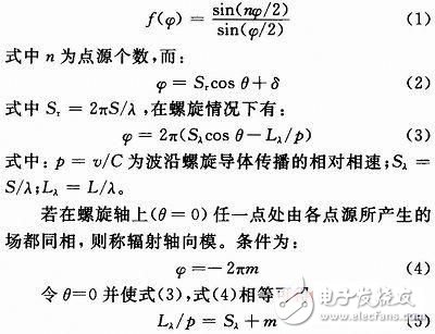
A spiral antenna is a broadband traveling wave antenna that radiates circularly polarized waves. According to the structure, there are two kinds of stereo spiral and plane spiral. The radiation characteristics of a three-dimensional helical antenna mainly depend on the ratio of the screw diameter D to the wavelength λ. When D/λ<0.18, the maximum radiation direction of the antenna is perpendicular to the helix axis, which is called normal mode radiation or fundamental mode radiation, and when 3/4π
1 Axial mode helical antenna theory and design
1.1 Axial Mode Helix Antenna Theory
The spiral geometry is shown in Fig. 1. The spiral parameters used to describe the spiral parameters are: the diameter D of the spiral, the pitch S between the adjacent spirals, the number of spiral turns n, and the diameter d of the spiral conductor. Other parameters deduced from these parameters are spiral perimeter C=πD, helix angle α=arctan(S/(πD)), length of each revolution, and the axial length of the spiral A=nS.

Assume that a uniform amplitude unidirectional traveling wave is carried on the n-turn helical antenna conductor along the radial axial model. According to the principle of multiplication of the directional diagram, the far field pattern is equal to the unidirectional pattern multiplied by a column of n isotropic point sources. The array factors that make up the linear array are equal to the pitch of the spiral. When the spiral is very long (nS/λ>1), the array factor sharp changes much more than the unidirectional pattern, so the far-field pattern of the long spiral can approximate the source pattern of this point. The array factor of the array of n isotropic point sources is:
Equation (5) is the relationship between the required length of the radial axial mode and the pitch, where m is the order of the maximum transmission mode for axial radiation. The relative phase velocity obtained by introducing the helix angle α when m=1:
p=1/[sinα+(cosα/Cλ)] (6)
If the point source phase is configured using the Hansen & Woodyard condition of the enhanced directional end-fire array, equation (4) becomes:
φ=-(2πm+π/n) (7)
The relative phase velocity p becomes:
John D. Kraus verified 3/4 through extensive experiments
For the 3/43 single-wound axial mode helical antenna, John D. Kraus obtained some empirical formulas through extensive experiments and studies, and later passed H. E. King and J. L. Wong corrected to obtain the half power beam width HP, gain G, impedance R and axis ratio AR, as follows:

1.2 axial mode helical antenna design
LAN communication antenna design requirements: S11 bandwidth is greater than 100 MHz, gain is greater than 10 dB, half-power beam width is less than 30°, and circular polarization axis ratio is less than -3 dB. The diameter of the wound spiral conductor ranges from 0.005λ or less to 0.05λ or more. 5 GHz corresponds to a wavelength of 60 mm so that d has a range of 0.3 mm
2 Antenna simulation results and analysis
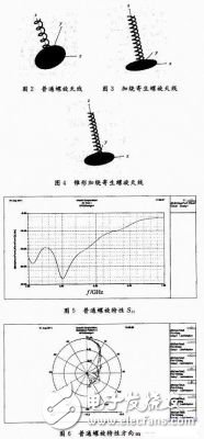
After detailed optimization and simulation, the general spiral S11, directional diagram, and axial ratio are shown in Fig. 5 to Fig. 7, respectively.

The three types of antennas S11, directional patterns (φ=0°), and axial ratios (φ=0°) were compared, as shown in FIGS. 8 to 10 . The ordinary spiral antenna has a very wide bandwidth, and the parasitic spiral structure limits the bandwidth of the antenna, but there are more than 100 MHz available bandwidth above and below the 5 GHz band, and the tapered structure is slightly wider than the ordinary structure. For the directional pattern, the general spiral half-power beam width with a parasitic structure is 25° and the gain is up to 11.52 dB. The general spiral beam width is also 25° and the gain is slightly lower at 10.6 dB. The spiral antenna with a parasitic structure has poor directivity, and the half-power beam has a width of 30° and a gain of 8.19 dB. For the axial ratio, the helical helical antenna with parasitic structure has the best performance, which is less than 3 dB when φ=0° and θ<80°. The other two antennas have an axial ratio of less than 3 dB when the pitch angle θ<30°. The simulation results are in good agreement with empirical formulas (11)-(14). Can be applied to wireless LAN communication systems.
3 Conclusion
According to the wireless LAN communication antenna design requirements, three axial-mode helical antennas are designed for use in the 5 GHz band. Among them, the ordinary spiral antenna has a very wide bandwidth (3 to 5.6 GHz), while the parasitic spiral antenna has a higher gain, but its bandwidth is much narrower than that but it can meet the requirement of greater than 100 MHz. The gain is lower, but the circular polarization characteristics are better. Can choose according to more application needs.
We design, engineer and fabricate mold tooling, both standard and custom. We continuously design custom tooling to satisfy our customer needs. These tools are built for machines such as Newbury, Autojector, Ameriplas, Multiplas, etc. Our Solidworks 3D design capabilities represent the leading edge in the industry.
We provide training and know-how to our customers. We offer this unique advantage to companies interested in On-site training to assist in the development of in-house capabilities. Our company can become your "over -mold engineering department" and can provide quick turn-around, high quality for customers' the complete cable set with wire harness, plastic, silizone o-ring, metal terminal, or plate, etc. Try to give you the whole supporting service.
Molded Plastic Products,Waterproofing Plastic Box,Plastic Connectors,Plastic Cap,Plastic Bushing
ETOP WIREHARNESS LIMITED , https://www.wireharnessetop.com