1. Check the preparation work before installation
Before installation, the supervision engineer and Party A’s engineers should check whether the entry road is unblocked, and if necessary, require the general contractor to construct a simple transportation channel to connect to each installation point, and the construction site layout should meet the requirements of safe and civilized construction. At the same time, the installation unit's construction equipment arrangement should be checked, and the installation unit should be urged to inspect the construction equipment to ensure good condition. Before the high-voltage equipment arrives at the site, the power distribution room, trenches, and foundation channel steel should be completely completed.
1), power distribution room
Power distribution room: before the construction of the power distribution room, the detailed drawings required for the construction of the power distribution room should be handed over to the construction party (within 2 weeks after the contract is signed, the focus should be on the confirmation of the location, content and completion time of the drawings by the customer), and During the construction of the power distribution room, the technical personnel of our party or the cooperating unit shall supervise on site to avoid construction errors. (The construction of the power distribution room takes about 2 weeks)
2) Foundation
The channel steel placement position should correspond to the equipment air duct reserved in the power distribution room, and the minimum distance between the equipment and the wall must be clear (the distance is too close, and the cabinet door of the equipment cannot be opened). (It takes about 2 days for channel steel welding, our technicians must be present to guide)
3), the equipment arrives at the scene
If the power distribution room and the foundation are not built, the equipment must have a storage location (rainproof or provide necessary rainproof materials).
2. Installation
2.1 The doors and windows of each power distribution room must be tight and the room clean.
2.2 The distribution board is installed firmly. The equipment in the disk is firmly connected with each component.
2.3 The grounding of the panel and cabinet should be firm and good. Openable panels and cabinet doors equipped with electrical appliances should be reliably connected to the grounded metal frame with flexible wires.
2.4 The terminal box should be installed firmly and well-closed. The installation position should be easy to check. When installed in rows, they should be arranged neatly.
2.5 The wiring in the distribution board should be horizontal and vertical, the screws should not be loose, and the wire ends should be in good contact.
2.6 The components in the disc are reliably fixed without looseness, and the contacts are free of oxidation and burrs
.
2.7 The connecting parts of the secondary circuit should be made of copper. Specific requirements for connection:
2.7.1 The electrical circuit connection (bolt connection, plug connection, welding, etc.) should be firm and reliable.
2.7.2 The end of the cable core wire and the equipped wire should be marked with its loop number; the number should be correct, the writing should be clear and not easy to decolor.
2.7.3 The wiring is neat, clear and beautiful; the wires are well insulated and no damage.
2.7.4 There should be no joints for the wires in the panel and cabinet.
2.7.5 There is generally one wire on each side of each terminal board, and no more than two wires.
2.8 The electrical clearance between the charged body of the secondary circuit of 400 volts and below or between the charged body and the ground shall not be less than 4 mm. The leakage distance should not be less than 6 mm.
2.9 The wires used to connect movable parts (door appliances, console boards, etc.) should still meet the following requirements:
2.9.1 Multi-strand flexible conductors should be used, and there should be adequate margin when laying.
2.9.2 The wire harness should have a reinforced insulation layer (such as an outer plastic tube, etc.).
2.9.3 When connecting with electrical appliances, the ends should be twisted tightly, and should not be loose or broken.
2.9.4 Use clips to fix both ends of the movable part.
2.10 The control cables and their core wires introduced into the panel and cabinet shall meet the following requirements:
2.10.1 The cables introduced into the panel and cabinet should be arranged neatly to avoid crossing, and should be firmly fixed so as not to subject the connected terminal board to mechanical stress.
2.10.2 The steel tape of the armored cable should not enter the coil or cabinet; the end of the cut off of the armored steel tape should be tied tightly;
2.10.3 For control cables used for transistor protection, control and other logic circuits, when shielded cables are used, the shielding layer should be grounded; if shielded cables are not used, the base spare core wire should be grounded;
2.10.4 The rubber insulated core wire should be protected by an insulating tube;
2.10.5 The cable cores in the trays and cabinets should be connected vertically or horizontally and arranged regularly, and must not be cross-connected at will; spare cores should be left with appropriate margin.
2.11 Where insulated wires may be contaminated by oil, oil-resistant insulated wires should be used, or oil-proof measures should be taken.
2.12 Safety technical requirements for power distribution devices:
2.12.1 When two or more power sources are used for power supply, an interlocking device should be installed between the main input and the tie switch of each power source (except those dispatched by the power supply department).
2.12.2 An interlocking device shall be installed between the isolating switch of the 10 kV indoor complete set of equipment and the corresponding circuit breaker.
2.12.3 The color arrangement of the power distribution device should comply with the column requirements:
(1) The color arrangement of the circuits in the same power distribution device should be as consistent as possible.
(2) The hard bus bars should be painted, and their colors are: a phase yellow; b phase green; c phase red; zero line black.
(3) The soft busbars should be marked separately.
(4) The wire in the interval of the power distribution device should be left with a place to hang the temporary grounding wire, and the corresponding color paint should not be painted here.
2.13 The installation of the terminal board should meet the following requirements:
2.13.1 The terminal board should be undamaged, firmly fixed and well insulated.
2.13.2 The terminal board should be easy to replace and convenient for wiring.
2.13.3 If the circuit voltage exceeds 400V, the terminal board should have sufficient insulation and be painted with a red mark.
3 check
3.1 Inspection
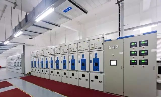
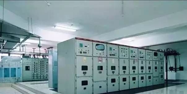
3.1.1 Whether the ventilation, lighting and safety fire protection devices of the high and low voltage distribution room are normal.
3.1.2 The switchboard door is tight and free from damage, and the switchboard is clean and dust-free.
3.1.3 All power distribution panels in the station must be listed for warning.
3.1.4 The signal lights, electric bells, and emergency electric bells of the signal device loop should display accurately and work reliably.
3.1.5 Whether the voltage and current of the motor in the power distribution cabinet are normal (not exceeding 5% of the rated value).
3.1.6 Whether the bus bar and each contact are overheated, whether the temperature indicating wax sheet is melted, and whether the insulating bakelite is burned out.
3.1.7 Whether the electrical components in the switch cabinet have abnormal smells and noises during operation.
3.1.8 Whether the oil level of the oil injection equipment is normal, whether the oil color becomes darker, and whether there is oil leakage.
3.1.9 Whether the indications of meters, signals, indicator lights are correct, and whether the position of the relay protection pressure plate is correct.
3.1.10 Whether the relay and DC equipment are operating well.
3.1.11 Whether the connection wire of the grounding and zero connection device is loose or disconnected.
3.1.12 Whether the insulation of porcelain bottles, insulating sleeves, and wall sleeves are clean, and whether there are cracks and discharge marks.
3.1.13 Whether the mechanical interlocking of the circuit breaker and the isolating switch is flexible and reliable. If an electromagnetic interlocking device is adopted, it is necessary to energize to check whether the electromagnetic lock action is flexible and the opening and closing are accurate.
3.2 monthly inspection
A comprehensive inspection, dynamic closing test of the magnetic starter, and sensitivity test of the relay shall be done once a month for each operating part and electrical part of the motor and power distribution cabinet.
3.3 annual inspection
Conduct a relay test on the motor and power distribution cabinet every three years, which is verified by the power supply personnel.
3.4 Inspection and maintenance
3.4.1 Inspection and maintenance shall be carried out once a month.
3.4.1 The line for maintenance after power failure must be listed first, and then work to show a warning.
3.4.2 The motor, cable and power distribution panel must be well grounded, and the grounding resistance should not be greater than 4 ohms.
3.4.3 Measure the DC impedance of the motor and make an AC withstand voltage test. Current transformer and voltage transformer are tested for withstand voltage and converter ratio.
3.4.5 The cable shall be subjected to DC withstand voltage leakage test; the relay shall be overhauled and reset.
3.4.6 The oil switch shall be disassembled for inspection, repair, adjustment and tightening; the arrester shall be subjected to a pressure test.
Application scenario of horizontal bending
When the cable tray is laid indoors, if the straight section of the installation cable tray goes to the corner, it needs to make a turn. In this scene, the horizontal turn should be completed by connecting the horizontal elbow with the cable cable tray on both sides of the wall at 90 degrees respectively. If there is no other object at the corner of the corner, the Angle of horizontal bending can be 90°. If there are other objects, it can be designed to be 30°, 45°, 60° to fit on it.
Rayhot Technology Group Co.,Ltd , https://www.cnrayhot.com