H-bridge drive. In addition to the h-bridge driver specifications given in Table B61, the parameters in Table B62 must also be specified. See Figure B37.
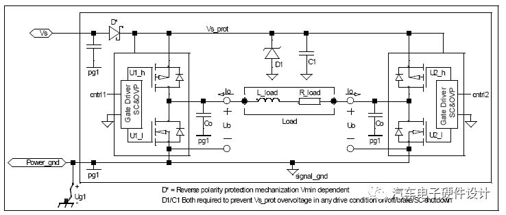
Figure B37: Discrete output, h-bridge.
The protection components D1 and C1 must be suitable and designed to protect the used MOSFET and MOSFET drive. When the load energy is suddenly out of control in the off state, it will be released due to overvoltage or overcurrent triggering.
Table B61: Discrete output, h-bridge, electrical characteristics.
| parameter | symbol | Condition Note 1 | lowest | Typical value | maximum | unit | Remarks |
| Uoh_min Highly effective state | Tmin to Tmax, Umin to Umax. | Vs-1 | Vs | V | In Ioh_max | ||
| Uol_max Low effective state | Tmin to Tmax, Umin to Umax. | 0 | 1.0 | V | In Iol_max | ||
| Leakage current, inactive state | Ioleak_max | Maximum rating | 10 | uA | Vs_prot reaches signal_gnd through the h bridge. | ||
| Inrush current, active state | Isurge | Maximum rating | 10× Io_max | A | |||
| Output frequency | f | 0 | 128 | 400 | Hz | Loads connected by wiring harness. | |
| Output frequency | f | 0 | 25 | KHz | Drive comprehensive load | ||
| Need protection | The battery voltage is short and the ground is short. | ||||||
| Allow protection | Overcurrent and/or high temperature shutdown | ||||||
| Anti-static protection Note 2 | Processing/Drive | kV | Should comply with GMW3097 |
Note 1: Umin, Unom and Umax are defined by the electrical code letters of the GMW3172 code string.
Note 2: Input protection should pass the GMW3097 verification requirements, and ceramic capacitors of A0805 size are available on the connector plug.
Table B62: Discrete output, h bridge, other parameter requirements.
| parameter | symbol | condition | lowest | Typical value | maximum | unit | Remarks |
| Output current, active state (active low) | Iol_max | Maximum rating | A | ||||
| Output current, active state (active low) | Iol_min | Minimum rating | A | ||||
| Output current, active state (high effective) | Ioh_max | Maximum rating | A | ||||
| Output current, active state (high effective) | Ioh_min | Minimum rating | A | ||||
| Avalanche energy processing | E | ½×I2×L | J | I = Ioh_max L = L_load_max | |||
| Output frequency | f | Maximum rating ±1% | Hz | ( | |||
| Output frequency | f | Maximum rating | Hz | (If not continuous) | |||
| Working period | At trigger level = 0.5 (Uoh-Uol) + Uol. | % | (Default 5% 95%) | ||||
| Point-to-space ratio accuracy | At trigger level = 0.5 (Uoh-Uol) + Uol. | % | (Default 0.5%) | ||||
| Active state on time | t_on_max | Maximum rating | mS | Repetitive signal per cycle (if not continuous) | |||
| Load Resistance | R_load_min | Minimum rating at -40°C | W | ||||
| Load inductance | L_load_max | Maximum rating at -40°C | H | Activated if the mechanical transmission |
Ceramic Rod,Ceramic Bar,Zro2 Ceramic Stick,Alumina Ceramic Rod
Yixing Guangming Special Ceramics Co.,Ltd , https://www.yxgmtc.com