1. Time relay:
TON enable = 1 count, when the count reaches the set value (counting up to 32767), the timer bit = 1. Enable=0 reset (timer bit=0).
TOF enable = 1, timer bit = 1, the counter is reset (cleared). Enable negative transition from 1 to 0, the counter starts counting, when the set value (stop counting), the timer bit=0. As shown below:
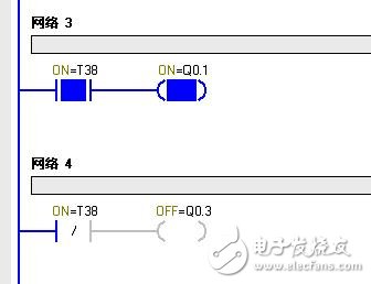
Figure 1: When enable = 1, the contact action diagram of TOF (T38)
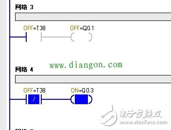
Figure 2: After the enable is disconnected, after the count reaches the set value, the contact action diagram of TOF (T38) (where the T38 normally open contact is when the enable changes from 1 to 0, the counter counts to the set value Becomes 0 later)
TONR enable = 1, the counter starts counting, when the count reaches the set value, the counter bit = 1. The enable is disconnected, the counter stops counting, and the counter bit is still 1. When the enable bit is 1, the counter counts on the basis of the original count.
The above three counters can be reset by reset command.
Quadrature counter phase A leads phase B by 90 degrees, counting up
Phase B leads Phase A by 90 degrees, counts down
When you want to change the counting direction (increasing or decreasing), just swap the wiring of phase A and phase B.
2. Decoding instructions and encoding instructions:
The execution results of decoding instructions and encoding instructions are shown in the figure:
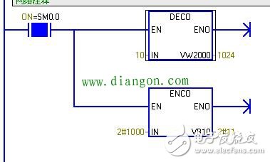
DECO sets the tenth position of VW2000 to zero (1024 in decimal), the lowest bit of ENCO input IN is 1 is the third bit, and 3 is written into VB10 (binary 11).
3. Form filling instruction (ATT)
The enable terminal (EN) of the S7-200 form filling command (ATT) must use a rising or falling edge command (that is, add a rising or falling edge after I0.1 in the figure below). If you simply use a normally open touch Click, the following error will appear:
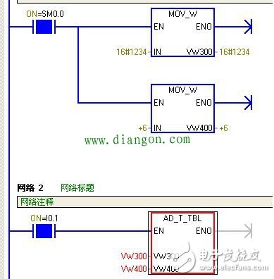
This point is also not explained in the programming manual and needs to be noted. The same applies to other table commands.
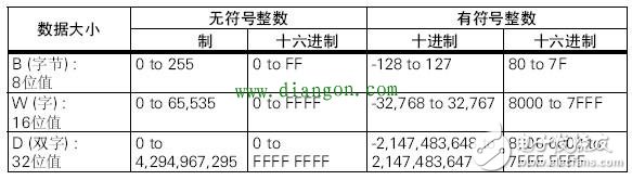
Four, data conversion instructions
When using the data conversion command, you must pay attention to the data range. If the data range is large, it is converted to a small data range. Be careful not to exceed the range. The following figure shows the size and range of the data.
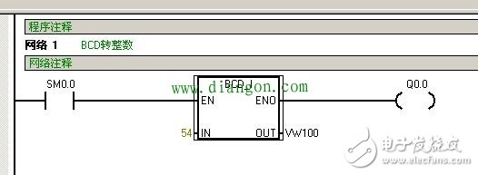
(1) Convert BCD code to integer (BCD_I)
The BCD code is converted into an integer. I understand it like this: treat the value of the BCD code as a decimal number, and then regard the conversion of BCD to an integer as the conversion of a decimal number to a hexadecimal number. As shown in the figure below, the BCD code is 54 and it is 36 when converted to an integer.
The conversion of an integer to a BCD code (I_BCD) is just the opposite, which is regarded as a conversion from hexadecimal to decimal.
(2) Convert integer to double integer (I_DI)
This problem needs to be noted that: after the integer is converted to a double integer, the sign bit is extended, because the precision of the integer is less than the precision of the double integer. After the conversion, the double integer represents the bit occupied by the integer value, and the rest of the space is the sign bit filling. For example, after the integer 45 is converted to a double integer, the base binary representation is: 2#0000_0000_0000_0000_0000_0000_0010_1101, and the integer -45 is converted to a double integer: 2#1111_1111_1111_1111_1111_1111_1101_0011.
Five, do not reuse PLC output coil
Normally open contacts and normally closed contacts in the basic logic instructions, as enabling conditions, can be used repeatedly indefinitely both in syntax and in actual programming.
The PLC output coil, as a driving element, can be used grammatically for unlimited times. But it should not be used in actual programming and should be avoided. Because, among the repeatedly used output coils, only the last one in the program is valid, and the others are invalid. The output coil has the last priority.
As shown in Figures 1 and 2.
The output line is not reused
The output line is not reused
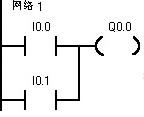
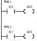
Figure 1: The output line is not reused Figure 2: The output line is not reused
As shown in Figure 1, the output coil Q0.0 is for single use, which means that any one of the two normally open contacts of I0.0 and I0.1 is closed, and the output coil is electrically output.
As shown in Figure 2, the output coil Q0.0 is repeatedly used, and is reused twice in network 1 and network 2. The purpose is the same as that shown in Figure 1, requiring any one of the two normally open contacts I0.0 and I0.1 Closed, the output coil is energized and output.
First of all, you need to be sure that the program shown in Figure 2 is grammatically correct. However, among the output coils repeatedly used by Q0.0, the network 2 is really effective, and the network 1 is redundant and invalid. In other words, whether I0.0 is closed or opened, it has no effect on Q0.0, and whether Q0.0 is energized is determined by I0.1.
This is because in a scan cycle of the PLC, the refresh of the PLC output points is executed after the program is executed. In a scan cycle, even if I0.0 is closed and I0.1 is disconnected, when the PLC program executes network 1, The output point Q0.0 mapping memory is 1, and when the network 2 is executed, the output point Q0.0 mapping memory becomes 0 again. After the diangon.com program is executed, the PLC output point will be refreshed, and the final output point Q0.0 will not output after power failure. Similarly, in a scan cycle, I0.0 is disconnected, I0.1 is closed, and the output point Q0.0 image memory will finally be 1. When the PLC output point is refreshed, the output point will be energized and output. Therefore, in the program shown in Figure 2, only I0.1 affects Q0.0.
Therefore, in PLC programming, repeatedly use the counting coil. Although it is grammatically correct, it should be avoided.
Several methods of setting and resetting and comparison
There are several methods for positioning and resetting. You can directly use set and reset instructions, you can also use data transfer instructions, table filling instructions, and even shift cycle instructions.
The specific application of these methods should also depend on the situation. Here is an example to explain their differences. It is required to set and reset the sixteen-bit output of Q0.0~0.7 and Q1.0~1.7.
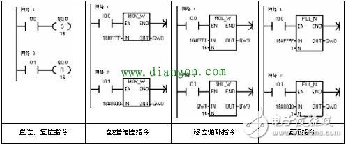
Several methods of setting and resetting
Among the above methods, in addition to shift and rotate instructions, other instructions are easier to understand.
The method of shifting and rotating instructions, setting the bit is to circulate 16 bits of 16#FFFF 16-bit constant to the left, and send the output word QW0 (composed of Q0.0~0.7, Q1.0~1.7), no matter how 16#FFFF is cycled , Or 16#FFFF, 16-bit output. The reset adopts a 16-bit left shift instruction for QW0 once in a scan cycle to move all the data in QW0 out (if it is a signed word, even the sign bit is also moved out), and the output is reset.
In the above method, directly adopting the method of setting and resetting can not only set and reset the bits in bytes, words, and double words, but also operate on the bits that do not form bytes, words, and double words. Data transfer instructions, shift cycle instructions, and fill instructions can only set and reset bits in bytes, words, and double words, and fill instructions can only operate on words.
For example, it is difficult to set and reset the seven-bit output of Q0.0~0.6. It is difficult to implement data transfer instructions, shift cycle instructions, and fill instructions. At this time, only the direct setting and reset instructions are used.
Germany Type Electronics Connection


Germany power strips distrbute power to multi devices, computer, refrigerator, etc at same time. The dural plastic housing(flame retadent PP merterial) stands 750 degree high temperature, children safety shutter, premium safety for you and your family. Right-angle plug type E can be flexibility used for suers and save space at same time. The KYFEN Germany USB power strips with USB type A or type C, deliver power to moblie phone, game machine or other mobile machine. KYFEN Germany extension cord socket got CE/GS/RoHS/REACH approved, comply with eu sales requirements.
Germany Type Electionics Connection,Power Strips,Power Extension,Power Distribution Unit
CIXI KYFEN ELECTRONICS CO.,LTD, , https://www.kyfengroup.com