The rapid development of FPGA technology and the support of VHDL (Very high speed integrated circuit Hardware Description Language) hardware description language make the VHDL description of intelligent control strategies (fuzzy logic, neural networks, genetic algorithms, etc.) and FPGA hardware implementation research become active. In terms of fuzzy logic control, Toralba et al. completed FPGA implementation of a fuzzy logic controller with 4 inputs, 12 memberships, and 64 rules. Cirstea et al. designed a fuzzy controller based on FPGA. This article mainly explains the design and implementation of a fuzzy PID controller based on FPGA. First, it introduces the working principle of FPGA, basic characteristics and the advantages of FPGA. Secondly, it describes the use of Altera's FPGA design to achieve a digital fuzzy PID controller, follow the small one. Get up and find out.
FPGA operating principleFPGA adopts the concept of logic cell array LCA, including three parts: configurable logic module CLB, output input module IOB and internal connection. The FPGA uses a small lookup table (16 & TImes; 1 RAM) to implement combinatorial logic. Each look-up table is connected to the input of a D flip-flop. The flip-flop then drives other logic circuits or drives the I/O. Logical functions can also implement basic logic unit modules for sequential logic functions. These modules are connected to each other or to I/O modules using metal wires. FPGA logic is implemented by loading programming data into internal static memory cells. Values ​​stored in memory cells determine the logic functions of logic cells and the connection between modules or modules and I/O, and ultimately determine the The function that FPGA can realize, when power up, FPGA chip reads the data in EPROM into the on-chip programming RAM, after finishing disposing, FPGA enters the working state. After power-down, the FPGA recovers to a white chip and the internal logic disappears. Therefore, the FPGA can be used repeatedly. FPGA programming does not require a dedicated FPGA programmer, just use a common EPROM, PROM programmer. When you need to modify the FPGA function, you just need to change the EPROM. In this way, the same FPGA, different programming data, can produce different circuit functions. The FPGA is set by the program stored in the on-chip RAM. Therefore, the on-chip RAM needs to be programmed during operation. Users can use different programming methods according to different configuration modes.
1) FPGA design ASIC circuit (application-specific integrated circuit), users do not need to shoot production, you can get a shared chip.
2) The FPGA can be used as a mid-sample for other fully custom or semi-custom ASIC circuits.
3) The FPGA has a rich set of internal flip-flops and I/O pins.
4) FPGA is one of the devices with the shortest design cycle, lowest development cost, and minimal risk in ASIC circuits.
5) FPGA uses high-speed CMOS technology, low power consumption, compatible with CMOS and TTL levels.
The advantages of FPGAAdvantage 1:
Greater degree of parallelism. This is mainly achieved through both concurrent and streaming technologies.
A: Concurrency refers to the repeated allocation of computing resources so that multiple modules can perform calculations independently at the same time. This is similar to the current multi-core and SIMD technologies. But relative to SIMD technology, FPGA concurrency can be performed between different logic functions, not limited to performing the same function at the same time. A simple example is that using SIMD can perform multiple additions at the same time, while FPGA can perform multiple additions and multiplications at the same time and any logic you can design.
B: Streaming is performed by segmenting tasks and executing them at the same time. In fact, this is similar to the CPU, except that the CPU is running between instructions and the FPGA is running between tasks or can be said to be inter-threaded.
Advantage two:
customizable. The internal logic of the FPGA through the Lookup Table can be simply understood as a hardware circuit. Customizable means that users can implement their own logic circuits within the allowable range of resources. Under normal circumstances, the task running on the hardware circuit is faster than the software, for example, to compare the size of a 64-bit high 32-bit and low 32-bit, under the CPU requires two regions instructions, two bits and instructions, A shift instruction is a compare instruction and a writeback instruction, and only one comparator is required under the FPGA.
Advantage three:
Reconfigurable. Reconfigurable means that the logic inside the FPGA can be changed according to requirements, reducing development costs. At the same time, using FPGAs to reuse resources saves more space for servers than using multiple fixed ASIC modules.
Design and Realization of Fuzzy PID Controller Based on FPGAFirst, the principle of the controller
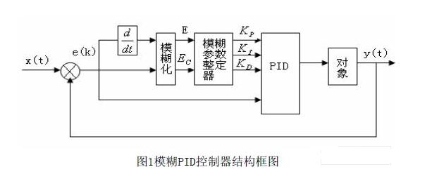
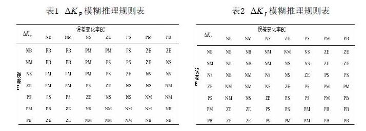
Fuzzy self-tuning PID controller structure: It is a combination of fuzzy controller and traditional PID controller. Using the idea of ​​fuzzy inference judgment, according to different deviations and deviation rate of change, the PID parameters KP, KI and KD are automatically adjusted online. After acquiring the new KP, KI, and KD, the PID controller outputs the control amount to the control object. From this fuzzy PID controller block diagram shown in Figure 1.

Second, the controller's VHDL layered design
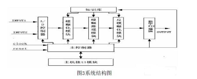
Fuzzy PID controller is mainly composed of A/D controller, fuzzification module, fuzzy inference module, anti-fuzzification module, rule memory, and digital PID operation. Its structure is shown in Figure 3. The VHDL design process is described with respect to the establishment of major modules such as fuzzy modules, fuzzy inference modules, and anti-fuzzification modules.
1, fuzzy module
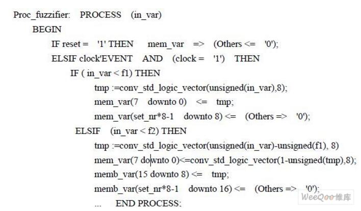
The function of the fuzzification module mainly includes two parts: transforming the precise amount of the input into the corresponding scope of the territorial domain; transforming the amount of input that has been transformed into the scope of the discourse to perform fuzzification, mainly calculating the subordination of each input. degree. Since the membership functions of the variables all use isosceles triangles, the bottom edge width and the midpoint of the bottom edge can determine all the information of the membership function. One byte is used to represent the bottom width of each linguistic variable (half of the actual width). Three bits are used to represent the midpoint of the bottom edge. This part of the information is stored in two tables. Based on the information in the two tables, the membership of the input variable can be calculated. In order to achieve the degree of membership calculation, an adder, a subtractor, and a divider need to be used. The result of the calculation is definitely a decimal (known by the nature of the degree of membership). For the sake of convenience, the calculation result of the molecule is left shifted by 8 bits. In this way, the calculation result of the numerator is 16 bits, the denominator is 8 bits, and the calculation result is 8 bits. VHDL for some of its inputs is described as follows:
2, fuzzy inference module
The fuzzy inference module is the core of the fuzzy controller. It infers the input fuzzy quantity and turns it into the output fuzzy quantity. Fuzzy inference uses Mamdani reasoning, also known as Max-Min reasoning, which is the maximum and minimum reasoning, because it mainly includes the maximization module and the minimization module. For a two-input system, up to four language values ​​and four degrees of membership are output. In this way, for a two-input system, up to four fuzzy rules are activated. The above process is the process of rule matching. Rule matching requires a minimal operation, the Min operation. Rule merging is to merge the same fuzzy rules of the back piece. The rule merging requires maximizing operation, ie, Max operation. The four membership function values ​​calculated by the fuzzification module are input to the comparator through the multiplexer through the control signal; after the other two control signals are decoded, one of the membership function registers is selected, and the output minimum value is selected at the same time. Comparator; The output of the comparator is then entered into the membership function register. In this way, after four cycles, a minimal operation is completed. Since the VHDL description is simple, it is omitted here.
3, anti-fuzzification module
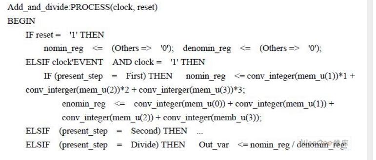
Anti-fuzzification usually uses a gravity method. Since the membership function uses 8 as a binary representation and the number of rules involved is at most 4, the molecular operation requires four 8-bit x 2-bit multipliers and three 10-bit adders. The denominator requires three 8-bit adders. In addition, a 12-bit/10-bit divider is also needed. The design method of the divider is the same as the design method in the fuzzification module. The multiplier design is similar to the divider design method. The corresponding VHDL is described as follows:
4, digital PID arithmetic module
The digital PID operation is mainly the operation of addition, subtraction, and multiplication. Using the original code algorithm to design the digital circuit undoubtedly increases the complexity of the circuit. It is much simpler to design using complement arithmetic. Addition and subtraction can all be implemented with the same summing circuit. There are many ways to design a multiplication circuit. Considering the problem of saving FPGA device resources, the BOOTH algorithm is used. It mainly involves accumulator overflow processing and decimal arithmetic processing.
Third, the test results
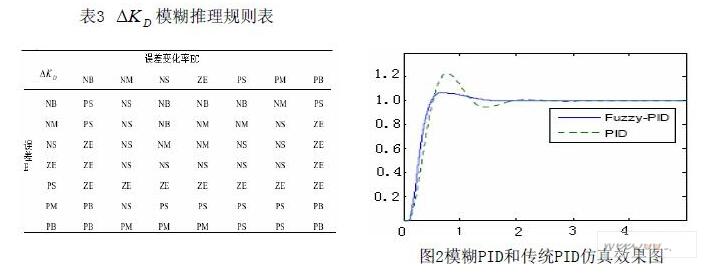
Using the FIS editor provided by MATLAB's fuzzy control toolbox, a mamdani-type fuzzy controller is established, and a Simulink toolbox is used to establish a fuzzy PID control system simulation model. The system step response obtained by the simulation is shown in Fig. 2. It can be seen from the figure that the Fuzzy-PID control adjustment time is short, the overshoot is small, the curve is smooth, and it has strong anti-interference and robustness.
After each module program is compiled and optimized, the Quartus II software integrates and generates a netlist file, and finally downloads it to the EP1C6Q240C8 chip of the Cyclone series of Altera Corporation. The actual test shows that the fuzzy PID controller control effect is significantly better than the ordinary PID controller.
Fourth, the conclusion
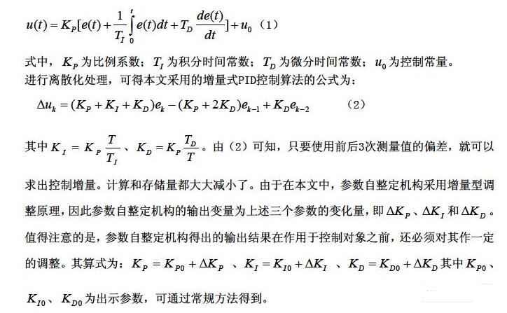
This article uses Altera's FPGA design to implement a digital fuzzy PID controller. The PID part adopts the incremental algorithm, the fuzzy control part adopts off-line calculation and on-line look-up table, which greatly improves the control effect of the ordinary PID controller without increasing the hardware resource consumption. At the same time, FPGA as a single controller to achieve fuzzy self-tuning PID control, programming specifications, timing verification, flexible system modifications, and basically do not need to change the hardware, is to achieve a single chip or small system intelligent control strategy of a new and effective way.
Cmos Barcode Scanner,2D Cmos Barcode Scanner,Koolertron 2D Cmos Barcode Scanner,Koolertron 2D Cmos Barcode Scanner Man
Guangzhou Winson Information Technology Co., Ltd. , https://www.barcodescanner-2d.com