Thanks to advances in filter synthesis technology and electromagnetic simulation software, today's bandpass filter designs have become relatively simple and fast. If you understand the advantages and disadvantages of various types of resonator structures and coupling methods, then with some design techniques, you can design various types of filters with great flexibility.
Based on the above reasons, we decided to solve these problems by using an LTCC filter that uses a 2.4G 200MHz wifi band. I don't have much experience in LTCC. I can only design and simulate an ideal LTCC filter based on my understanding of the fundamental theory of the filter and the characteristics of the LTCC process. There are irrational places that are welcome to discuss.
Careful friends can see that there are only one step in these articles on various types of bandpass filters.
ADS or Excel calculates the group delay required for each coupling factor
Input group delay judgment input coupling size and resonator size
Double cavity group delay judging coupling coefficient between stages
The overall electromagnetic simulation, curve fitting to determine the direction of optimization, the final design of the filter.
1. 2.4G BW=200MHz 4th Order LTCC Filter Design
Discussed with the brothers of Jiaxing Jiali Electronics that the LTCC materials commonly used in domestic research institutes were dupon 951 (dielectric constant 7.8) and ferro A6M (dielectric constant 5.9). However, the cost is very high. Generally private companies will use their own powder. This article uses Jiaxing Jiali's own dielectric constant of 10 to design its own powder.
1) Calculate the group delay required for each coupling coefficient
The delay characteristics of the coupling coefficient groups required for calculating the filter through the ADS or excel widget (some feedback link failures, re-issued here) are shown in Figure 1.
Download Link: https://pan.baidu.com/s/1vLKV3cqvpqApsP376Kbn0g Password: u8rm
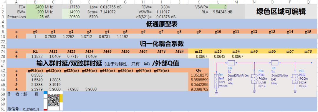
Figure 1 Ideal parameter calculation for filter design
2) Resonator size and input-output coupling determination
If you want to give a slightly accurate initial value, you can roughly estimate the initial size through the transmission line theory. Here, the resonator size and the input-output coupling are obtained by direct modeling simulation. The model shown in Figure 2 is built in a sonnet. The model uses multiple layers of interleaved plates to achieve capacitance, multilayer windings to achieve inductance, and input coupling through taps on the inductor. The initial parameters of the structure in the model are given arbitrarily according to the process conditions and experience.

Figure 2 LTCC resonator model
Through a modeling, the simulation finds that the frequency is low. At this time, it is necessary to reduce the inductance or capacitance according to experience to increase the frequency to an appropriate position. After several iterations or scans, it is relatively easy to design an accurate resonator size and tap position.
The iteratively designed tap position and the resonator structure are shown in Figure 2. Through the input delay, the resonant frequency and the coupling amount can be accurately determined during the iteration. The rest is to adjust the structure based on theoretical basis or experience.

Figure 3 Accurate Resonator, Tap Structure, and Simulation Results
3) Interstage coupling size design
The resonator 1 is duplicated and placed in the corresponding position. Because it is a lumped LC resonator, the inter-stage coupling can be coupled through inductance or capacitance. Here, capacitive coupling is performed to establish a capacitively coupled double resonator model as shown in FIG. 4 , and empirically, it is adjusted to the desired double resonator group delay value.
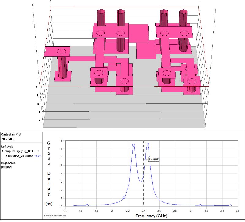
Figure 4 Double resonator group delay simulation
4) Preliminary simulation of the overall model
Due to the design of the fourth-order filter, a full filter model can be drawn symmetrically after the double-resonator simulation is performed, and the 23-resonator capacitive coupling is added after symmetry. (In the case of no cross-coupling, the inter-stage coupling is reduced sequentially. Small, but also about the middle level symmetry), the model is shown in Figure 5, preliminary simulation is shown in Figure 5. It can be seen that the preliminary simulation result is not ideal and the filter needs to be optimized and adjusted.

Figure 5 Overall Model and First Simulation Results
5) Number extraction optimization filter
The application of parameter extraction in designing the bandpass filter in the sixth paragraph "parameter extraction design band-pass filter" is described in detail, but phase loading of the joint is not considered in the sixth issue of the article. For loading, please refer to the article "An Analytical Approach to Computer-Aided Diagnosis and Tuning of Lossy Microwave Coupled Resonator Filters", which has certain limitations when extracting parameters. Removal of phase loading is also the place specified in this article.
The core of removing phase loading in the paper is to determine the phase loading by making the ideal coupling matrix model equal to the echo group delay and transmission phase at the far end of the filter in the simulated or measured S2P file.
The parameter extraction model shown in FIG. 6 is established in the ADS. By tuning the control, the coupling matrix model and the S2P result curve are overlapped as much as possible to give a reasonable initial value. By tuning the control, the coupling matrix response and the S2P file echo time delay and transmission phase at 1.5G to 2G are equal (or 90 degrees out of phase, based on the coincidence of the real imaginary part of S11 and S33 to determine 90 degrees or 0 degrees) The result after tuning is shown in Figure 7. Coupling matrix extraction was performed through the ADS optimization control. The comparison results of the curve fitting are shown in Fig. 8. It can be found that the coincidence degree of the curve fitting is very good. At this time, the adjustment direction of the filter model can be obtained by comparing the extracted coupling matrix with the ideal coupling matrix.
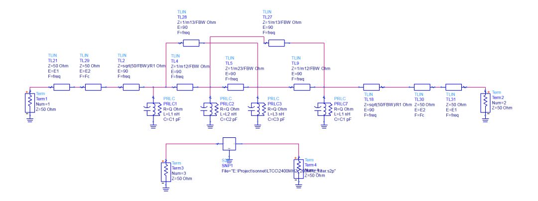
Figure 6 ADS model for parameter extraction
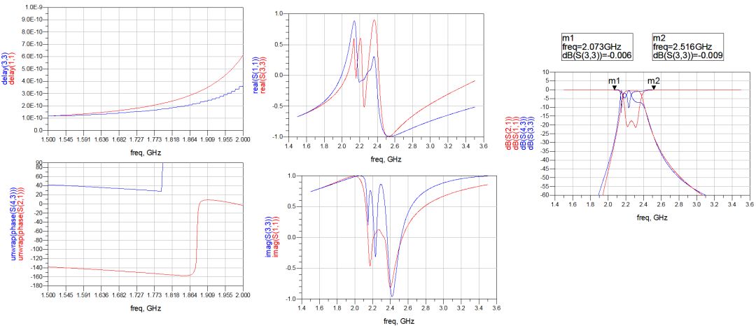
Figure 7 Remove phase loading diagram

Figure 8 Comparison of curve fitting results after removing phase loading
After one extraction, the results of the extraction are shown in Table 1. It can be seen that the frequency of the resonator 2 and the resonator 3 is both low, while the 23 coupling is small. First, reduce the inductance of the 2 and 3 resonators (capacitive coupling, change the capacitance to easily cause coupling changes), and increase the frequency of these two resonators.
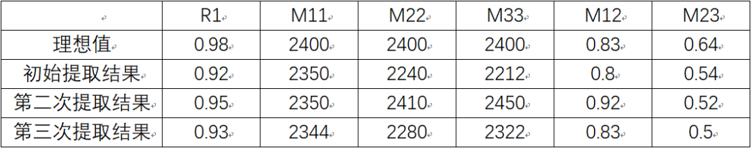
Reduce the inductance and pass the second extraction. The result is shown in Table 2. It is found that the adjustment amount is too large. Take the first adjustment of the middle value of the inductance and make another adjustment. The adjustment results are shown in Fig. 9. It can be seen that the overall filter results are converged, and the ideal response curve can be obtained after many parameter extractions and optimizations are performed.
Table 1 First results
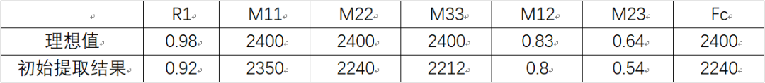
Table 2 The results of the second extraction

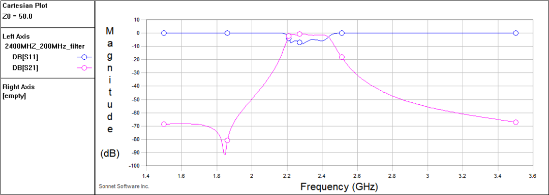
Figure 9 The result of the second adjustment
Table 3 The results of the third extraction
We believe that confidence always comes from the outside.We never let up on the quality of our productsWe use professional storage technology experience to configure this brand new SSD product, using 3D NAND TLC chip, with high-performance SMI (Silicon Motion) master control chip, all efforts to improve the performance of every operation.
m.2 ngff sata 2280, sata for laptop speed ,ssd 128gb 256gb
MICROBITS TECHNOLOGY LIMITED , https://www.hkmicrobits.com