Voltage drop, also known as voltage or potential difference, is expressed as U, in volts (V), which is the physical quantity that describes the power of an electric field to move a charge to do work.
When the charge flows, the energy of the charge is released in the circuit, and the connected components in the circuit and circuit absorb the energy of the charge. After energy absorption, the energy released by the charge itself becomes smaller, and people use the voltage drop to measure the ability of the charge to release energy in the circuit. When a current flows through the circuit, a certain voltage drop will occur in each segment of the circuit, and the voltage drop represents the amount of electrical energy that the charge flows through the small segment (or is expressed as absorbed by the small segment of the circuit).
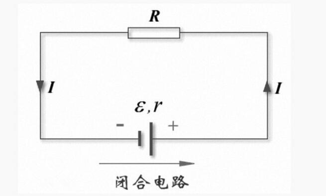
How to measure and calculate the voltage dropA part of the voltage of a power supply through a line or other part of the transmission voltage will be consumed to reduce, this part of the reduction is the voltage drop of the line, measuring the voltage at the beginning of the power source and the voltage at the end point, the difference between the two It is the voltage drop.
To give a simple example, for example, the substation output voltage is 220V, and your home voltage is 215V, then the voltage drop from this substation to your home is 220V-215V=5V.
First calculate the resistance R of the line. U loss = I*R. I is the load current.
In general, when the line length is not very long, due to the very limited voltage drop, the “pressure drop†problem can often be ignored. For example, the line has only tens of meters. However, if cable voltage drops are neglected on some relatively long power lines, the voltage may be too low to start the device after laying the cable, and the device may not be started at all; or the device may start but it is in a low voltage operation state for a long time. Damage to the device.
Longer power lines need to consider the issue of pressure drop. The so-called "long line" generally refers to the cable line is greater than 500 meters. Pressure drop should also be considered in applications where high voltage accuracy is required.
Reason for voltage dropFor power devices, such as generators, transformers, and other power cables, when the transmission distance is long, for example 900m, the “voltage drop†of the first library's network voltage should be considered. Otherwise, the cable procurement, installation, etc. Because the pressure drop was not taken into consideration, the equipment could not be started normally, resulting in engineering losses.
The voltage drop of the power line is due to the resistance of the conductor. Because of this, no matter what kind of material (copper, aluminum) the conductor will cause a certain voltage loss of the line, and this loss (voltage drop) is not greater than 5% of its own voltage is generally not generated on the electric drive of the line Consequences. For example, for a 380V line, if the voltage drop is 19V, that is, the circuit voltage is not lower than 361V, there will be no big problem.
Voltage drop â–³U=IR<5%U to meet requirements 220*5%=11V380*5%=19V

â–³u%=I*R
I=P/(1.732*U*COSθ)R=Ï*L/S
P: power, U: voltage; COSθ power factor; Ï conductor resistivity, 0.018S for copper core cable: nominal cross-section of the cable, L: line length
Allowable voltage drop in single phase: Vd=220Vx5%=11V
Allowable voltage drop in three phases: Vd=380Vx5%=19V
The formula for calculating the voltage drop is as follows:â–³U%=K*I*L*V0
K: three-phase four-wire system K = 3 under the root number, single-phase K = 1; I: operating current or calculated current (A)
L: line length; V0: voltage within the table (V/Am)
Estimating a voltage drop. useAccording to the load moment on the line, the voltage loss on the power supply line is estimated and the power quality of the line is checked.
2. MouthwashA reference data for estimating the voltage loss is proposed. Through some simple calculations, the voltage loss on the power supply line can be estimated.
The pressure loss is based on "kw. Meters" and 2.5 aluminum lines 20-1. The cross-section increases the moment of charge, and the voltage decreases squarely. 1 three-phase four-wire meter, copper wire multiplied by 1.7. 2
The inductive reactance load is high in pressure loss, and the effect of 10 cross-sections is small. If the force ratio is 0.8, 10 is increased by 0.2 to 1. 3
3. InstructionsThe voltage loss calculation is related to more factors and the calculation is more complicated.
In the estimation, the line has been selected according to the load conditions and the conductors and cross-sections, that is, the relevant conditions have been basically met,
Voltage Drop Calculation Method (http://). The voltage loss is measured as "a few percent of the rated voltage." The most important data for estimating the voltage loss is listed mainly, and how much "load moment" voltage loss will be 1%. When the load moment is large, the voltage loss increases accordingly. Therefore, first of all, the load moment of this line should be calculated.
The so-called load moment is the load (kW) multiplied by the length of the line (the length of the line is the guideline laying length “mâ€, ie
The path the line travels, regardless of the number of conductors on the line. ) The unit is "Kilowatts. Meters." :
1 First, the most basic basis for calculating the voltage loss is the load moment: kilowatts. Meter
Benchmark data: 2.5 mm2 aluminum wire, single-phase 220 V, load resistance (power factor of 1), and voltage loss of 1% per 20 "kw.m" load moment. This is the "2.5 aluminum wire 20-1" in the mouth.
On the basis of the 1% voltage loss reference, the cross-sectional area can be large, and the load moment can also be larger, changing in a proportional relationship. For example, 10 square millimeters of aluminum wire, cross-section 2.5 times 2.5 square millimeters, then 20 * 4 = 80 kilowatts. m, that is, the load moment of this wire is 80 kilowatts. In meters, the voltage loss was only 1%. The rest of the section is analogized.
"Lower squared voltage", for example, 36 volts, finds 36 volts equal to 1/6 of 220 volts. At this time, the line voltage loss of 1% of the load moment is not 20 kilowatts. m, and should be reduced by 1/6 of the square, ie 1/36, which is 20*(1/36)=0.55 kilowatts. Meter. That is, at 36 volts, every 0.55 kilowatts. In meters (ie every 550 watts. meters), the voltage loss is reduced by 1%.
Not only for lower rated voltages, but also for higher rated voltages. At this time, it must be increased by the square. For example, for a single phase of 380 volts, since the voltage of 380 volts is 1.7 times that of 220 volts, the load moment at a voltage loss of 1% should be 20*1.72=58 kilowatts. Meter.
From the above, we can see that: "The cross section increases the load moment and the voltage decreases the squareness." They are based on benchmark data "2.5 aluminum wire 20-1".
Other Custom Headers Overview
Custom Headers provide design flexibility, production efficiency while decreasing needed equipment assets
Antenk custom header family offers complete design flexibility to modify standard headers or develop new customized connectors to meet specific design requirements. Use the Custom Header Configurator or contact Antenk to find a custom header solution that caters to a wide variety of programs and volumes.
When OEMs perform pin insertion onto PCBs, they need to invest in stitching machinery to do so, and that increases manufacturing costs. Custom Headers make pin insertion unnecessary and eliminate the need for customers to invest in stitching machinery.
OEMs often look for ways to simplify their manufacturing processes to reduce costs and get products to market more quickly. Custom Headers reduce steps manufacturing process by providing headers with pins already inserted.
While press-fit headers typically meet automotive standards, the interface isn`t the most robust available. Soldered termination not only meets automotive standards, it also provides a stronger interface than press-fit.
Features and Benefits
Custom headers available-Delivers solution with custom housing, pins and blades designed for each application`s unique needs
Removes the need for stitching equipment-Creates a cost savings by decreasing capital investment needed for production
Custom Combo Blade/Pin Header
Pins and blades available in various sizes, counts, amperages and plating
Offers flexibility to meet specific design needs
Reduces number of components on PCB by enabling more pins and blades on one header
Custom Pin Headers
Specify attributes with online product configurator
Custom Pin Headers designed and sampled within days
Multiple mounting versions available, including vertical and right-angle, through-hole, vertical and horizontal SMT
Design to suit low profiles and flexible stacking requirements
Pins and/or blades inserted into header per specification-Provides time and cost efficiencies by simplifying the production process
Single and dual wafers-Customize for specific board stacking applications
Through-hole pins and SMT capable-Provides a more robust interface
Custom circuit sizes, variable pin lengths in 1.0mm increments-Provides customer flexibility
Applications
Automotive
Body Electronics
Engine train
Commercial Vehicle
Infotainment
Safety system
Consumer
Car audio system
GPS
Gaming Machines
Home Appliance
LCD TV
Set Top Boxes
Data/Communications
Desktop computer
Monitor
Notebook computer
Servers
Storage
Industrial
Lighting
Logic controller
Power
Robotic system
Switching system
Telecommunications
Base stations
Control room
Exchange station
Routers
Switches
Pcb Header,Other Male Header,Male Header Connector,Male Pin Header,Custom Male Headers,Custom Pin Headers
ShenZhen Antenk Electronics Co,Ltd , https://www.pcbsocket.com